Chapter 6 Adjustment
6-13
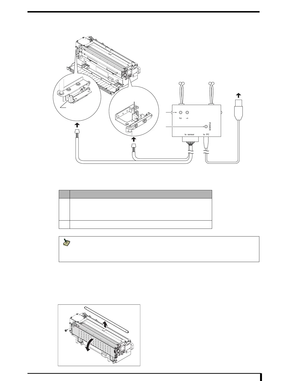
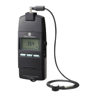
Sensor status detection jig
Sensor status detection jig will display the status of the sensor with the lamp by directly connecting it to
the detach detection sensor.
Adjustment method
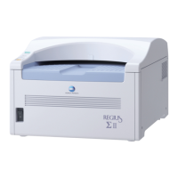
1 See " Removal Procedures (Page 5-11)" in "5.2.5 Removing/Installing the Optical Unit" to
remove the optical unit.
2 Remove the hot-cathode tube lamp.
3 Open the number 2 eraser cover.
•
- 1 screw (M4 x 12)
No. Function
1 Display the status of the connected detach detection sensor.
• Light on: ON (transparent)
• Light off: OFF (opaque)
2 It will light up on power ON.
Note
It has a buzzer that will go on when ON is detected on both sensors.
It will be in same condition and the buzzer will sound when the sensors are not connected, so
if you do want it to buzz when connecting the cables, connect the sensor cables before
connecting the USB cable.
1
2
Detach Detection
Sensor Bottom
Detach Detection
Sensor Top
To USB Connector
To Detach Detection Sensor