15 ELECTRICAL SYSTEM
118
V00371-10
–
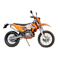
Using a coin, turn protection cap
2
all the way counterclock-
wise and take it off.
–
Remove combination instrument battery
3
.
– Insert the combination instrument with the label facing
upward.
Combination instrument battery (CR 2430) ( p. 148)
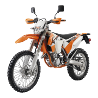
– Check the O-ring of the protection cap for correct seating.
V00372-10
–
Position protection cap
2
and turn all the way clockwise
using a coin.
– Press any button on the combination instrument.
The combination instrument is activated.
– Position the combination instrument in the holder.
– Mount and tighten the screws with washers.
Finishing work
– Install the headlight mask with the headlight. ( p. 115)
– Check the headlight setting. ( p. 116)
– Set kilometers or miles. ( p. 26)
– Set the combination instrument. ( p. 27)
– Set the clock. ( p. 27)
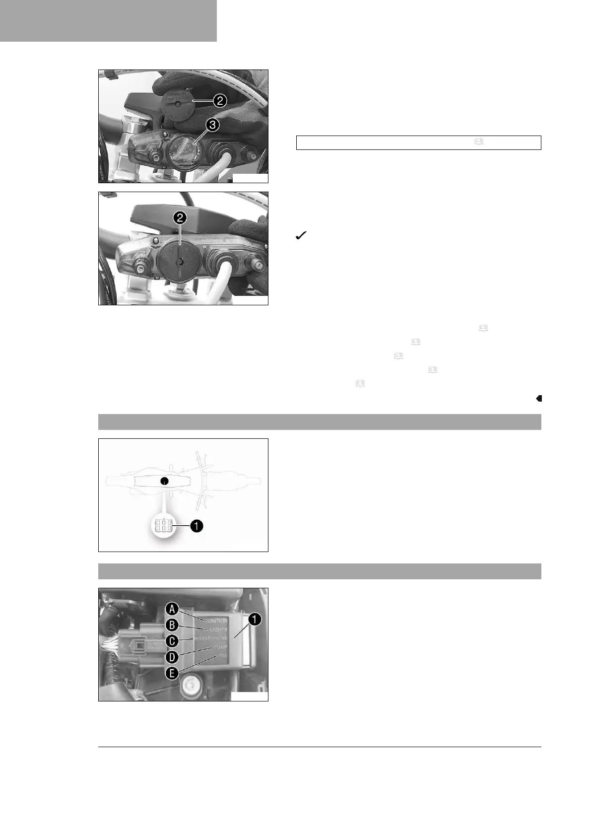
15.12 Diagnostics connector
H00933-12
Diagnostics connector
1
is located under the seat.
15.13 OCU
W00331-10
OCU
1
is located under the seat.
The OCU replaces the electronic fuses and relays.
All outputs are switched independently of the signals of the volt-
age regulator and ECU.
The outputs are deactivated individually in the event of overcur-
rent.
This enables easy error detection because the status of each out-
put is indicated via LED lights.
The OCU monitors the electronics system completely indepen-
dently.
As soon as an indicated error is rectified, the status light of the
OCU changes from red to green.

 Loading...