ENGINE
L3560, L4060, L4760, L5060, L5460, L6060, WSM
1-S72
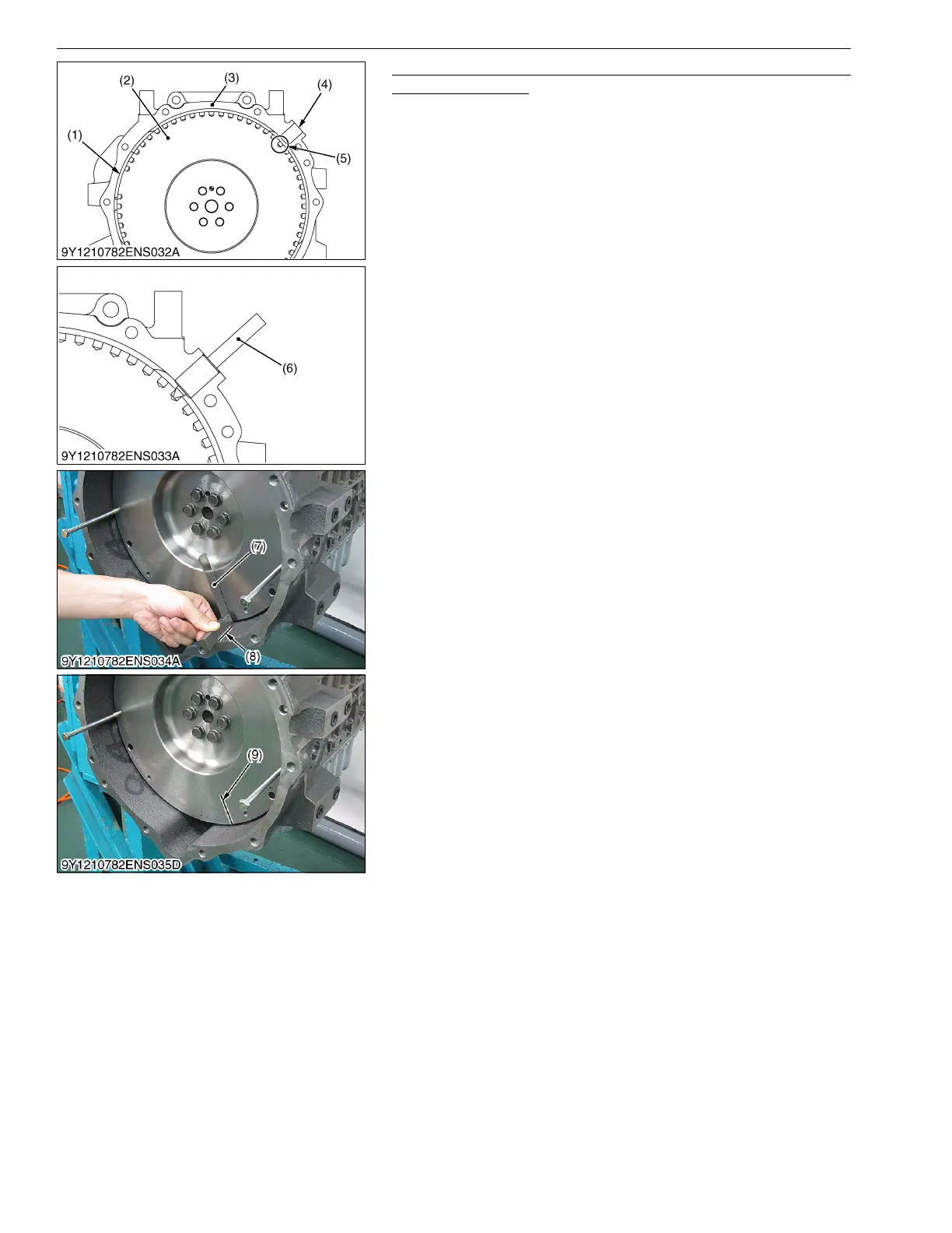
Confirmation of Crank Position Sensor Top Dead Center
Detection Position
1. Align the reference (17th for 3 cylinder models or 20th for 4
cylinder models) pulser hole (5) from the area where there is no
pulser hole (1) on the outer circumference of the flywheel (2)
with the crank position sensor mounting hole (4) on the flywheel
housing (3).
2. Insert a special tooling injection top correction jig (6) into the
crank position sensor mounting hole and align the center of
handle and pulser.
3. This position is the crank position sensor top dead center
detection position so position the tri-square (7) on the reference
line (8) set in the previous item and make a crank position
sensor top dead center detection position mark (9) on the
flywheel.
9Y1210824ENS0063US0
(1) Area where there is no pulser hole
(2) Flywheel
(3) Flywheel Housing
(4) Crank Position Sensor Mounting
Hole
(5) Reference Pulser Hole
(17th: 3 Cylinder Models)
(20th: 4 Cylinder Models)
(6) Injection Top Correction Jig
(7) Tri-square
(8) Reference Line
(9) Mark of Crank Position Sensor Top
Dead Center Detection Position
 Loading...


