ELECTRICAL SYSTEM
L3560, L4060, L4760, L5060, L5460, L6060, WSM
9-M17
3. ELECTRONIC CONTROL PANEL
[1] SYSTEM OUTLINE
The CPU does CAN (Control Area Network) communication with main ECU (Electronic Control Unit), engine ECU
(Electronic Control Unit), various sensors, switches and other related devices in order to give the functions that
accurately and timely provide the operator with various information necessary for tractor operation. The contents
include corrective procedure in case of an erroneous operation, precautions, and various alerts. If the tractor gets in
trouble, a damaged location, for example, is displayed with a message (sign) on the liquid crystal display or indicated
with a monitor lamp.
The electronic instrument panel displays the following items.
Various Information Display Function
LCD indication receives various data from each sensors:
• Position of range gear shift lever (HST).
• Position of shuttle lever (GST and Manual Transmission).
• Number of main shift lever (GST).
• Clock
• Traveling Speed
Normal Display Mode
Normal display receives various data from each sensors, and displays. The hour meter, the trip meter, the fuel
consumption, the PTO rpm, the HST setting, PM volume status and service inspect, etc. on the LCD which are basic
information necessary for the tractor operation.
1. Display 1 : Hour meter / Trip meter mode
2. Display 2 : Fuel consumption mode
3. Display 3 : PTO speed mode
4. Display 4 : HST mode (HST Only)
5. Display 5 : PM buildup mode
6. Display 6 : Service inspect mode
Information message (Attention Display at engine starting)
• Display the operator's guidance of PTO switch, shuttle lever, HST pedal and OPC at the engine starting on the
LCD.
Confirmation Message (Warning Display)
• Display when the fuel has got shorter than 6 L (1.5 U.S.gals, 1 Imp.qts) or so, the fuel level indicator and the
message appears on the LCD
• Display the engine overheat warning on the LCD and panel.
Fail-safe Function
• It is a function that the entire system operates safely when the part of system gets in trouble.
Error Display
• Displays the occurrence of DTC (Diagnostic Trouble Code) with the sign on the LCD by the self-diagnosis
function.
Indicator Control Function
• Controls the lighting and blinking of the warning indicator and the monitor indicator for operation.
(To be continued)
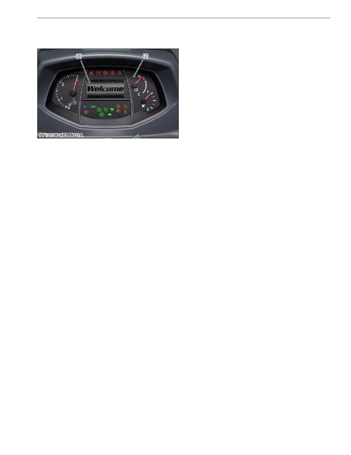
(1) Liquid Crystal Display (LCD) (2) Electronic Instrument Panel
(Intellipanel)
 Loading...


