ELECTRICAL SYSTEM
L3560, L4060, L4760, L5060, L5460, L6060, WSM
9-S53
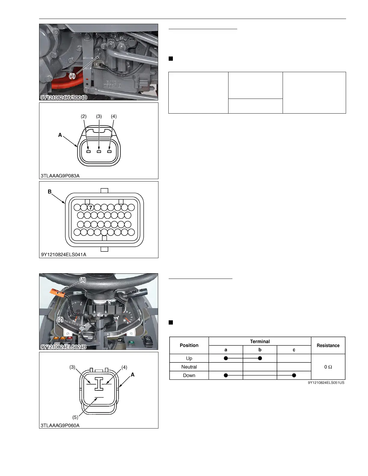
Traveling Speed Sensor
1. Measure the resistance between terminal 7 of main ECU
connector B and terminal 2 of sensor connector.
2. If 0 ohm is not indicated, the wiring harness is faulty.
• It is not necessary to adjust any kind of mode.
9Y1210824ELS0042US0
(8) Checking Sensor and Switch for HST
H-DS Lever Continuity
1. Remove the panel cover and steering post cover.
2. Disconnect the connector (2).
3. Measure the resistance between connector terminals, referring
to the table below.
4. If the measurement does not between as table, switch is faulty.
• It is not necessary to adjust any kind of mode.
9Y1210824ELS0048US0
Resistance
Terminal 2 of sensor
connector – Terminal 7
of main ECU
connector B
0 Ω
Terminal 3 of sensor
connector – Chassis
(1) Traveling Speed Sensor
(2) Terminal 1
(3) Terminal 2
(4) Terminal 3
A : Connector of Wire Harness Side
B : Main ECU Connector B (34P) of
Wire Harness Side
(1) H-DS Lever
(2) H-DS Connector
(3) Terminal a
(4) Terminal b
(5) Terminal c
A: Connector of H-DS Lever Side
 Loading...


