CLUTCH
L3560, L4060, L4760, L5060, L5460, L6060, WSM
2-S27
6. DISASSEMBLING AND ASSEMBLING
Clutch Assembly (Manual Transmission and GST)
1. Remove the clutch from the flywheel.
(When reassembling)
• Direct the shorter end of the clutch disc boss toward the
flywheel.
• Apply molybdenum disulphide (Three Bond 1901 or equivalent)
to the splines of clutch disc boss.
• Install the pressure plate, noting the position of straight pins.
• Align the center of disc and flywheel by inserting the clutch
center tool. (See page G-63.)
• Do not allow grease and oil on the clutch disc facing.
9Y1210824CLS0026US0
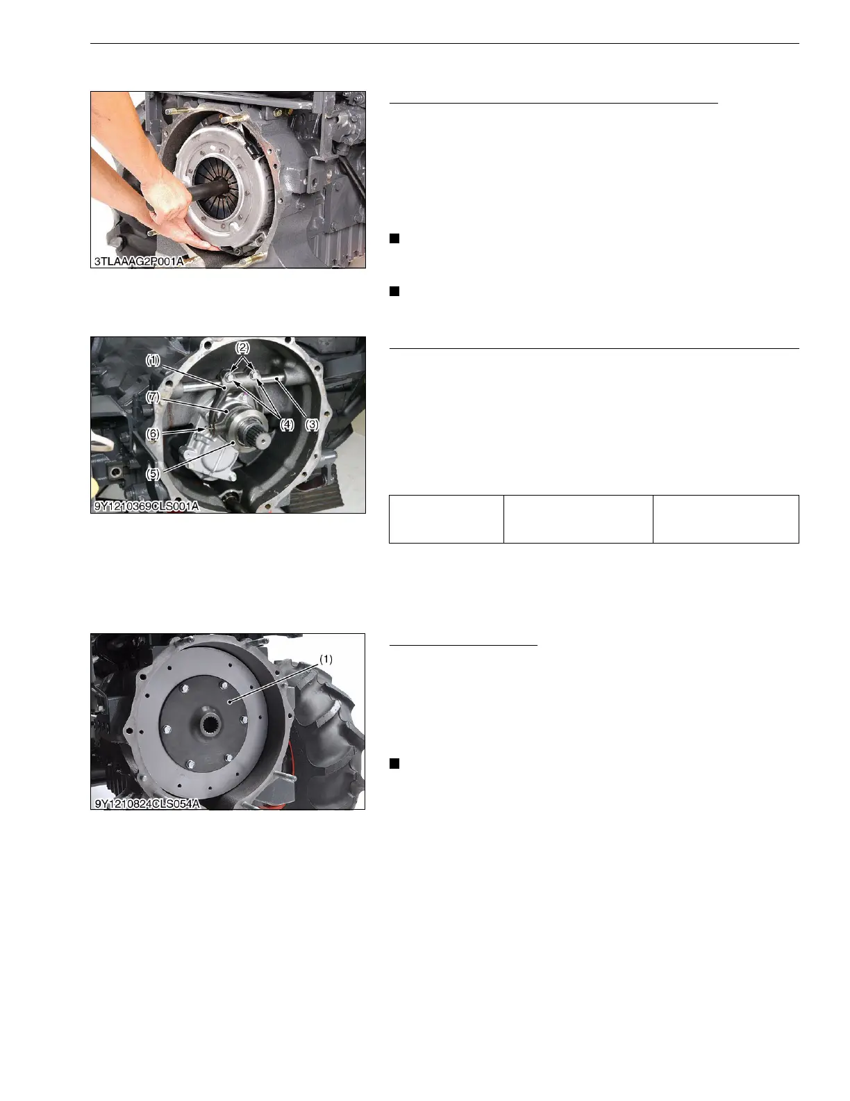
Release Hub and Clutch Lever (Manual Transmission and GST)
1. Draw out the clutch release hub (7) and the release bearing (5)
as a unit.
2. Remove the release fork setting screws (4) and fork keys (2).
3. Draw out the clutch lever (3) to remove the release fork (1).
(When reassembling)
• Make sure the direction of the release fork (1) is correct.
• Inject grease to the release hub (7).
• Be sure to set the snap pins (6).
9Y1210824CLS0027US0
Clutch Coupling (HST)
1. Remove the clutch coupling mounting screws.
(When reassembling)
• Mount the clutch coupling so that the short boss side faces to
the flywheel.
• Apply molybdenum disulphide (Three Bond 1901 or equivalent)
to the splines of clutch coupling boss.
• Align the center of disc and flywheel by inserting the clutch
center tool.
9Y1210824CLS0028US0
Tightening torque Release fork setting screws
24 to 27 N·m
2.4 to 2.8 kgf·m
18 to 20 lbf·ft
(1) Release Fork
(2) Fork Key
(3) Clutch Lever
(4) Setting Screw
(5) Release Bearing
(6) Snap Pin
(7) Release Hub
(1) Clutch Housing
 Loading...


