TRANSMISSION
L3560, L4060, L4760, L5060, L5460, L6060, WSM
3-M13
(2) Construction and Function of Components
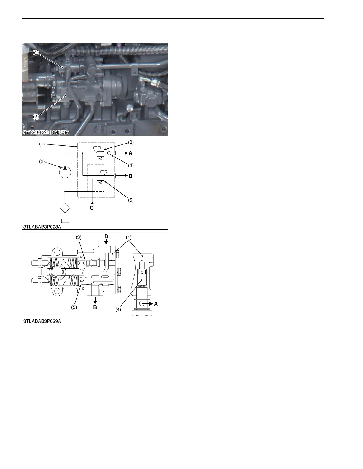
[A] Regulating Valve
The oil from the hydraulic pump for the power
steering system flows to the GST circuit to set the
pressure of the circuit. Other oil flows to the power
steering circuit.
The oil from the power steering hydraulic pump (2)
flows through the pressure reducing valve (5) to the GST
circuit. When the oil is filled into the circuit, the pressure
reducing valve (5) is closed to keep the pressure in the
GST system circuit to 2.45 MPa (25.0 kgf/cm
2
, 356 psi).
The oil from the power steering pump passes
through the regulating valve (3) and check valve (4), and
then it flows to power steering circuit. The regulating
valve (3) is provided to keep 2.94 MPa (30.0 kgf/cm
2
,
427 psi) at inlet pressure of the pressure reducing valve
(5) except when the power steering is operated. Thereby
getting 2.45 MPa (25.0 kgf/cm
2
, 356 psi) of the GST
circuit pressure.
9Y1210824TRM0017US0
(1) Regulating Valve Assembly
(2) Hydraulic Pump
(3) Regulating Valve
(4) Check Valve
(5) Pressure Reducing Valve
A: To Power Steering Circuit
B: To GST Circuit and PTO
Clutch Valve
C: From Power Steering
Circuit
D: From Hydraulic Pump
 Loading...


