ELECTRICAL SYSTEM
L3560, L4060, L4760, L5060, L5460, L6060, WSM
9-S52
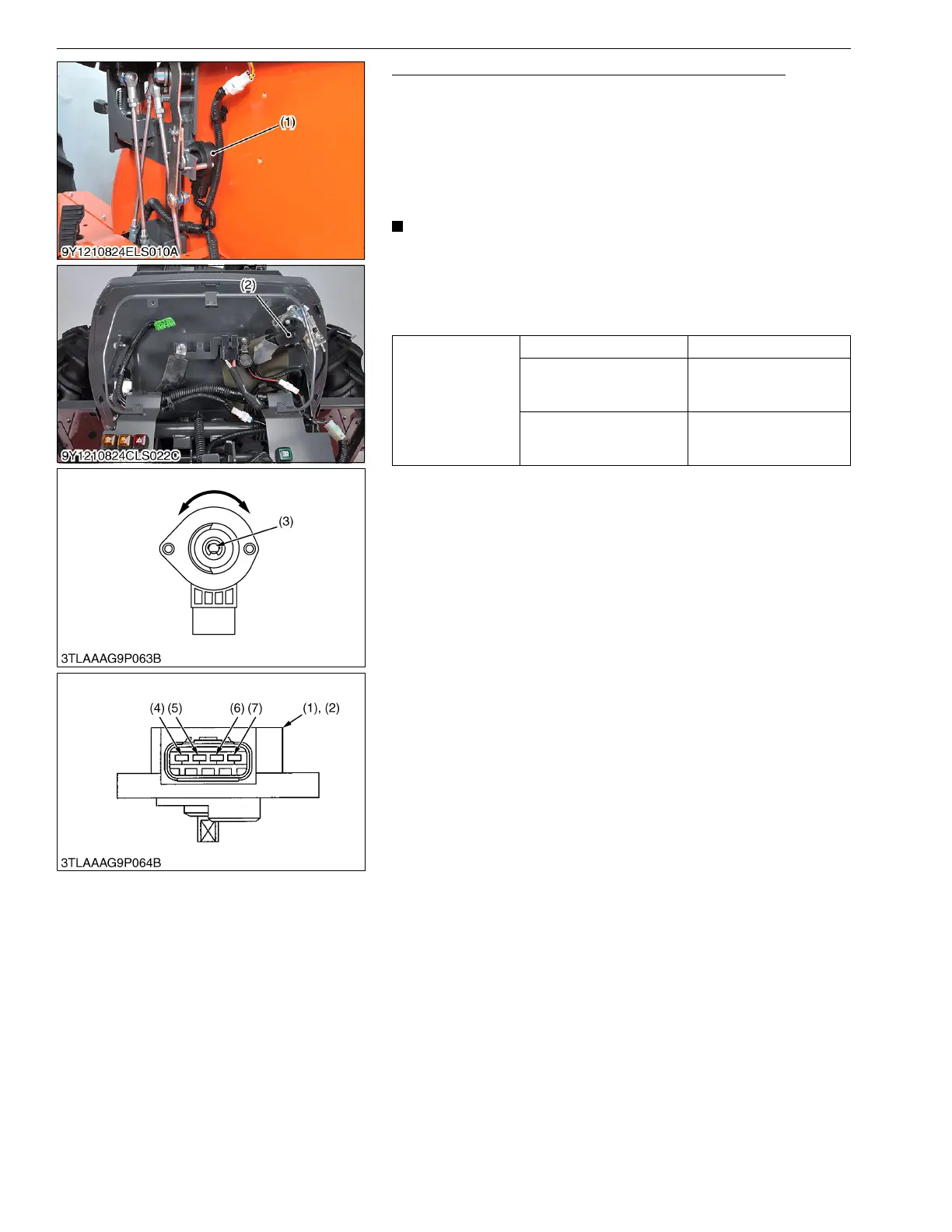
Hand Throttle Lever Sensor and Foot Throttle Sensor
1. Measure the resistance between terminal c (6) and GND (7).
2. Measure the resistance between terminal GND (7) and a while
slowly turning the sensor shaft.
3. Measure the resistance terminal GND (7) and b (5) while slowly
turning the sensor shaft.
4. It is OK if the resistance value approximates to the value shown
in the table below.
• When replacing the each sensor be sure to adjust the mode
"K".
(Reference)
• The change of resistance can be checking easily when an
analog tester is employed.
9Y1210824ELS0041US0
Reference
Terminal c – Terminal GND Approx. 1 kΩ
Terminal GND – Terminal a
Resistance is normal if
smoothly changing
Approx. 1 kΩ to 0 Ω
Terminal GND – Terminal b
Resistance is normal if
smoothly changing
Approx. 0 Ω to 1 kΩ
(1) Hand Throttle Lever Sensor
(2) Foot Throttle Sensor
(3) Sensor Shaft
(4) Terminal a
(5) Terminal b
(6) Terminal c
(7) Terminal GND
 Loading...


