TRANSMISSION
L3560, L4060, L4760, L5060, L5460, L6060, WSM
3-S79
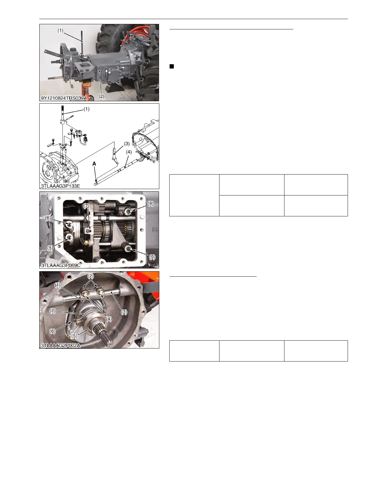
Shuttle Shift Arm and GST Valve Assembly
1. Remove the shuttle shift arm stopper screw, and then pull the
shuttle shift shaft (1) with shuttle shift arm (3) up.
2. Remove the GST valve (2) using two jack bolts.
3. Remove the shift pins (5) (6).
• Do not fall down the shift pin while disassembling.
(When reassembling)
• When reassembling the shuttle shift arm (3) to the shuttle fork
rod (4), be sure to install it to the groove "A".
• Place the 1-2 shift pin (5) and the 3-4 shift pin (6) at neutral
position, main range shift pin (8) at L position (forward) and
sub-range shift pin (9) at Hi position (rearward), and then
assemble the GST valve.
• Be sure to match the each shift pin and shift piston.
• Apply liquid gasket (Three Bond 1208C or equivalent) to joint
face of the GST valve assembly.
• Install the GST valve (2) by hand, and then tighten the screws.
Do not use the hummer.
• Replace the pipe (7) with a new one, if damaged.
9Y1210824TRS0054US0
Release Hub and Clutch Lever
1. Draw out the clutch release hub (7) and the release bearing (5)
as a unit.
2. Remove the release fork setting screws (4) and fork keys (2).
3. Draw out the clutch lever (3) to remove the release fork (1).
(When reassembling)
• Make sure the direction of the release fork (1) is correct.
• Inject grease to the release hub (7).
• Be sure to set the snap pins (6).
9Y1210824TRS0012US0
Tightening torque
Shift pin mounting screws
13 to 14 N·m
1.3 to 1.5 kgf·m
9.4 to 10 lbf·ft
GST valve mounting
screws
43 to 48 N·m
4.3 to 4.9 kgf·m
32 to 35 lbf·ft
(1) Shuttle Shift Shaft
(2) GST Value
(3) Shuttle Shift Arm
(4) Shuttle Fork Rod
(5) 1-2 Shift Pin
(6) 3-4 Shift Pin
(7) Pipe
(8) Main Range Shift Pin
(9) Sub-range Shift Pin
A: Fork Rod Groove
Tightening torque Release fork setting screws
24 to 27 N·m
2.4 to 2.8 kgf·m
18 to 20 lbf·ft
(1) Release Fork
(2) Fork Key
(3) Clutch Lever
(4) Setting Screw
(5) Release Bearing
(6) Snap Pin
(7) Release Hub
 Loading...


