 Loading...
Do you have a question about the KYMCO DINK 200i and is the answer not in the manual?
| Displacement | 175.1 cc |
|---|---|
| Cooling System | Liquid cooled |
| Transmission | CVT |
| Front Suspension | Telescopic fork |
| Front Brake | Disc |
| Rear Brake | Disc |
| Seat Height | 780 mm |
| Dry Weight | 148 kg |
| Front Tire | 120/70-12 |
| Rear Tire | 130/70-12 |
| Starter | Electric |
| Length | 2050 mm |
| Engine Type | Single cylinder, 4-stroke |
| Fuel System | Electronic Fuel Injection |
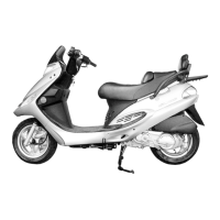
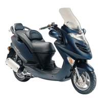
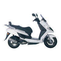
Detailed technical specifications for the DINK 200i model, covering dimensions, engine, fuel system, and more.
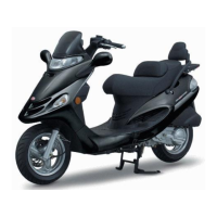
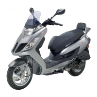
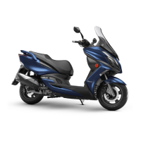
Detailed technical specifications for the DINK 125 model, covering dimensions, engine, fuel system, and more.
Essential safety and handling guidelines for servicing the vehicle.
Specific torque settings for critical fasteners across various engine and frame components.
Diagnostic guides for common engine performance issues and noises.
Step-by-step instructions for removing and installing various frame body panels and covers.
Procedures for the removal and installation of the exhaust muffler system.
Recommended intervals for routine inspection, cleaning, adjustment, and replacement of parts.
Procedures for inspecting, cleaning, and checking the spark plug gap and condition.
Instructions for inspecting and adjusting valve clearance while the engine is cold.
Guidance on engine oil selection, capacity, and checking the oil level.
Checks for brake fluid level, hose condition, and replacement/bleeding procedures.
Procedures for inspecting front and rear brake pad wear and replacement guidelines.
Common issues related to lubrication system problems like low oil level or poor pressure.
Detailed instructions for the removal, installation, and inspection of the engine oil pump.
Specified torque values for engine mounting and hanger bolts during installation.
Step-by-step procedure for safely removing the engine from the vehicle frame.
Procedure for reinstalling the engine, including torque specifications and system checks.
Inspection and replacement of engine hanger bushings and stopper rubber for wear.
Key specifications for cylinder head, camshaft, and valve components, including service limits.
Diagnosing issues related to poor cylinder head operation and engine noises.
Procedure for removing and installing the cylinder head cover, including O-ring.
Instructions for removing, installing, and adjusting camshaft holder and cylinder head nuts.
Steps for camshaft removal, inspection of lobes, and measurement of cam height.
Diagnosing issues related to cylinder compression and piston performance.
Procedures for removing the cylinder and piston, including inspection of rings and bore.
Common issues with the drive clutch and driven pulleys affecting engine operation.
Steps for removing and installing the left crankcase cover, gasket, and dowel pins.
Procedures for removing, inspecting, and installing the drive pulley, belt, and driven pulley assembly.
Diagnosing issues with the final reduction gears, such as abnormal noise or transmission failure.
Detailed steps for removing and inspecting the final reduction gears and components.
Procedures for replacing bearings in the transmission case cover and transmission case.
Common issues with the starter motor, including failure to start or incorrect rotation.
Steps for removing, inspecting, and installing the alternator stator and pulse coil.
Procedure for removing, inspecting, and installing the starter clutch assembly.
Diagnosing excessive engine noise, bearing play, or worn piston components.
Detailed steps for separating the crankcase halves for crankshaft access.
Procedures for inspecting crankshaft connecting rod clearance, small end ID, and runout.
Diagnosing issues like high engine temperature, coolant leaks, and gauge inaccuracies.
Steps for preparing, draining, refilling, and bleeding air from the cooling system.
Procedure for removing and installing the radiator, including hose and connector disconnections.
Inspection of the mechanical seal and removal/installation of the water pump and impeller.
Key specifications for the DINK 125 carburetor, including bore size, float level, and jet settings.
Common fuel system issues for the DINK 125, such as engine not starting or rough idling.
Detailed instructions for carburetor removal, installation, and disassembly.
Procedures for fuel pump removal, installation, testing, and disassembly for inspection.
Diagnostic guides for common DINK 200i fuel system issues, including engine stalls and poor performance.
Explanation of the CELP function and how it signals various fault conditions.
Steps for accessing and interpreting diagnostic codes using the ignition switch and throttle.
Instructions for clearing stored diagnostic trouble codes (DTCs) from the ECU memory.
Procedure to reset the throttle position sensor after throttle body replacement.
Guidelines for ECU removal, installation, inspection, and pin functions.
Procedures for T-MAP sensor removal, installation, and inspection of input voltage and resistance.
Common issues related to steering, suspension, and front brake performance.
Procedure for removing and installing the handlebar, switches, and master cylinders.
Steps for removing, inspecting, and installing the front wheel, including runout checks.
Checks for fluid level and hose condition, and procedures for fluid replacement and air bleeding.
Instructions for replacing the front brake pads and caliper mounting.
Procedure for removing, disassembling, inspecting, and assembling the front brake master cylinder.
Steps for caliper disassembly, piston removal, and caliper assembly with new seals.
Procedure for removing, inspecting, and installing the front shock absorbers.
Instructions for removing, inspecting, and installing the steering stem and bearings.
Diagnosing issues related to rear wheel wobble, poor brake performance, and suspension.
Checks for rear brake fluid level and hose condition, and procedures for replacement and bleeding.
Instructions for replacing the rear brake pads and caliper mounting.
Procedure for removing, disassembling, inspecting, and assembling the rear brake master cylinder.
Steps for caliper disassembly, piston removal, and caliper assembly with new seals.
Procedures for removing and installing the rear wheel, fork, and bearings.
Procedure for removing, inspecting, and installing the rear shock absorbers.
Diagnosing issues related to battery power, charging system failure, and intermittent power.
Procedure for battery removal, installation, voltage inspection, and charging.
Tests for current leakage and charging voltage to diagnose charging system faults.
Inspection of alternator charging coil resistance and continuity to ground.
Inspection of wire harness, battery line, ground line, and charging coil line.
Key specifications for spark plug, gap, ignition timing, and system types (ECU/CDI).
Diagnosing issues related to low peak voltage, no peak voltage, and no spark at the plug.
Procedure for checking primary peak voltage and ignition pulse generator resistance.
Diagnosing issues with the starter motor, including failure to turn or rotating without starting.
Procedure for inspecting, removing, and installing the starter motor assembly.
Instructions for replacing position light and headlight bulbs.
Procedure for removing and installing headlight bulbs, dust cover, and connectors.
Inspection of right and left handlebar switches for continuity.
Procedure for removing and installing the fuel unit, including float and meter checks.
Inspection, removal, and installation of the side stand switch for proper operation.
Complete wiring diagram for the DINK 200i model, illustrating electrical system layout.
Complete wiring diagram for the DINK 125 model, illustrating electrical system layout.