Function block library
7-237
SHB9300CRV EN 2.0
7.6.78.2 Cam data
l
Phase 1
– Start position:
X0 = 0 (master value)and Y0 = waiting position of the welding bar
–Endposition
X1 = WELD-LEN-C (time until welding bar reaches material)
Y1 = Welding bar in welding position (= start position of phase 2)
Note!
The slope of the characteristic should correspond to the max. possible acceleration of the welding
drive at max. line speed.
l
Phase 2
– The drive remains in welding position for the time set as WELD-TIME. For this, a waiting
phase (latch) is automatically set (independently of the line speed) between section 1 and
section 2. The waiting phase is not
added when the cam data is generated.
l
Phase 3
– The end position must be selected such that the max. acceleration of the welding drive at
max. line speed will not be exceeded (see also description phase 1).
l
Phase 4
– Add a standstill phase at the end of the motion profile.
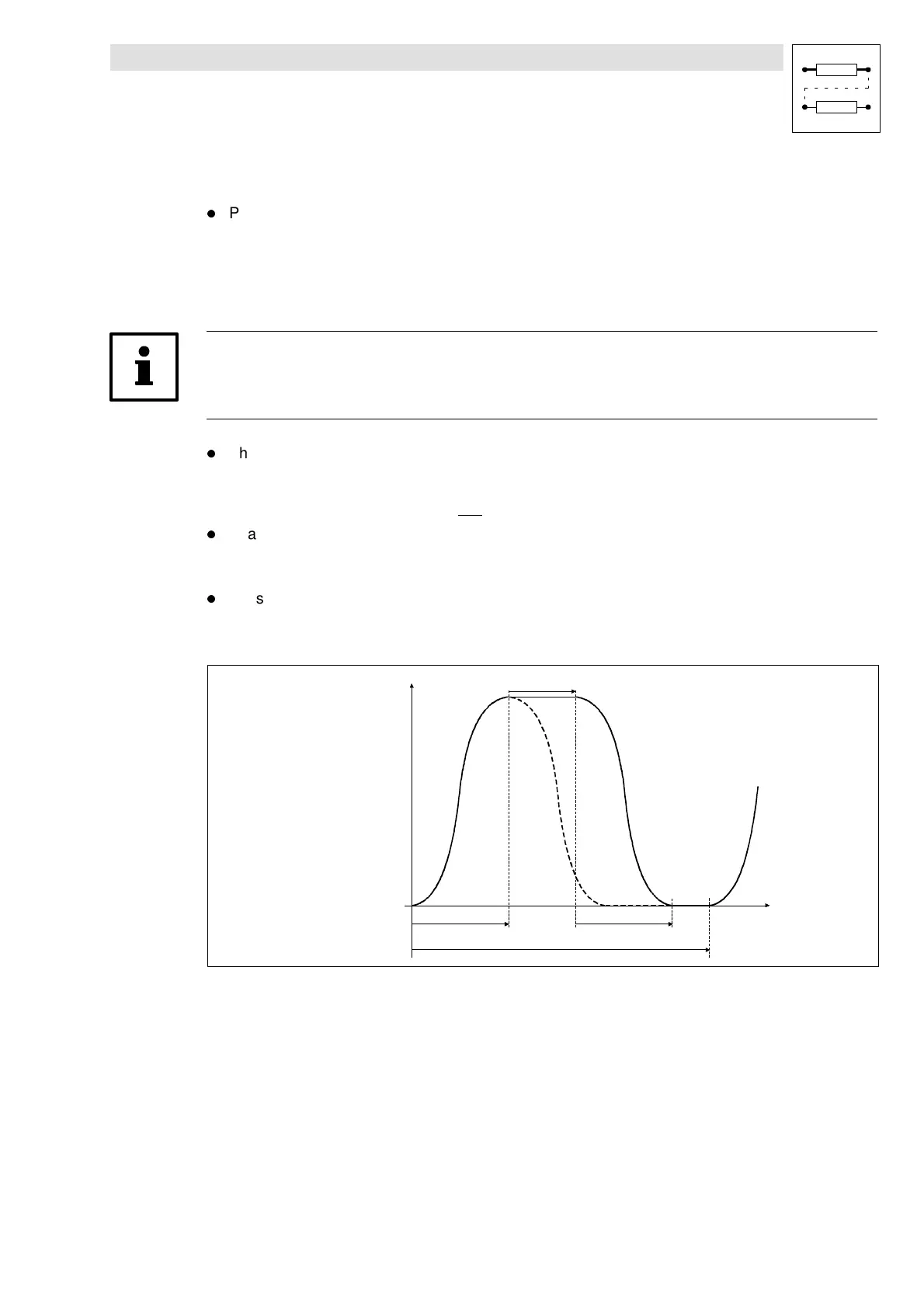
With the corresponding line speed, the following profile is generated:
Y-Pos
X-Pos
WELD-LEN-C
WELD-LEN-O
WELD-TIME
WELD-LEN
The selected welding time is converted into a distance.
The welding time set (WELD-TIME) automatically delays the opening phase (WELD-LEN-O) by the
selected welding time. The standstill phase at the end of the profile is automatically reduced. The
phases 1 and 3 are not affected. The higher the line speed, the shorter the standstill phaseat the end
of the profile.
 Loading...


