Driving modes and rigging for on-road driving
6.5 Installing/removing the outrigger beams
6 - 40 3 302 633 en Operating Instructions GMK5250L
27.09.2017
6.5.3 Preparations – for removal
Labelling the outrigger beams
Each outrigger beam is designed for just one installation point. If, for exam-
ple, you remove the outrigger beam on the rear left hand side, you must
mount the same outrigger beam on the rear left hand side again.
• Before you remove all outrigger beams for the first time, label them with
the correct installation point and if necessary, also with the serial number
of the truck crane.
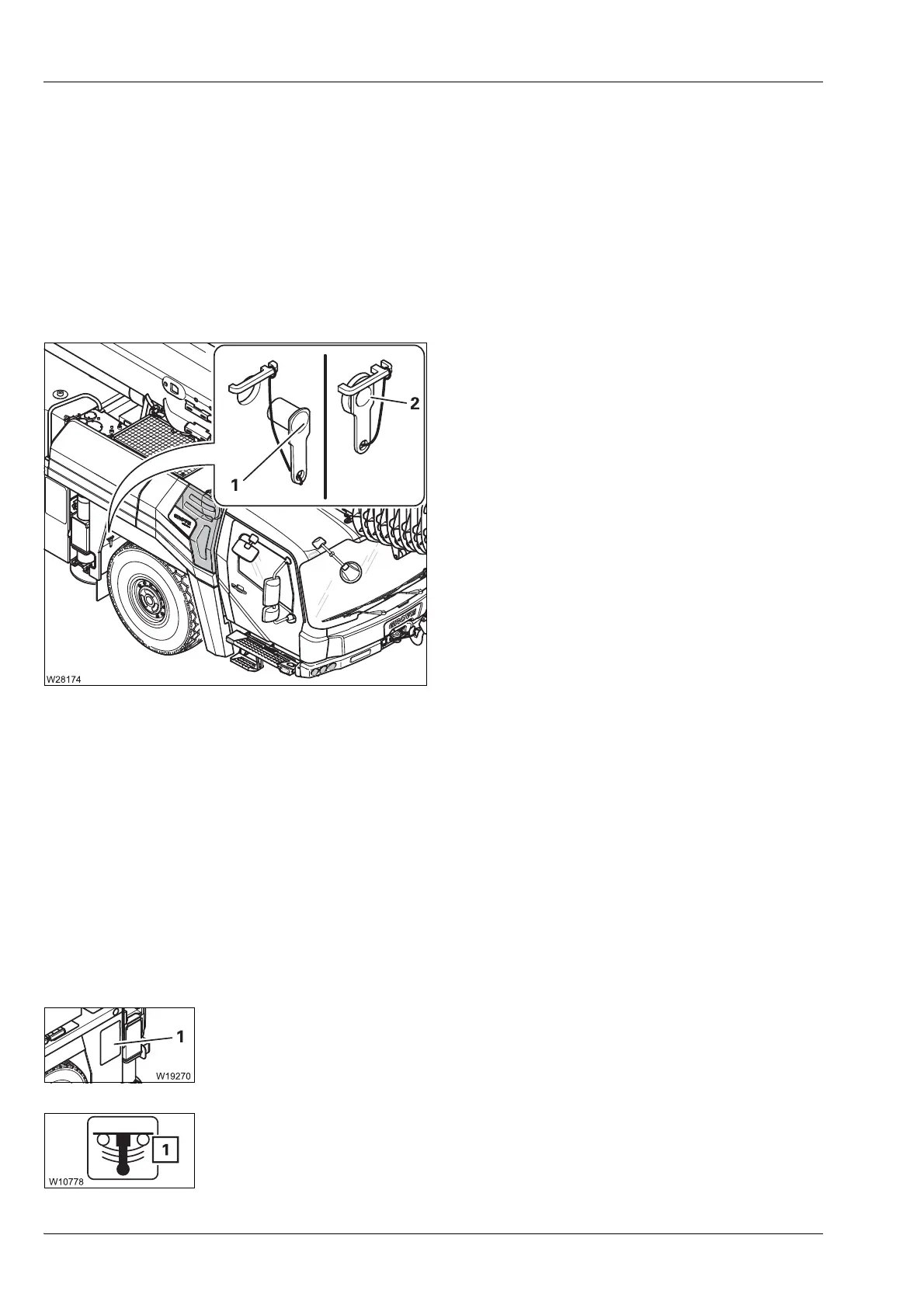
Release the outrigger beams
All outrigger beams are retracted.
• Pull out the pin (1).
Lock the outrigger beams together
• Insert the pins (2).
6.5.4 Preparations – for installation/removal using the auxiliary
crane
Prerequisites The following requirements must be met before mounting/removing the
outrigger beams:
– All rigging work which involves slewing the superstructure has been
completed.
– The parking brake is engaged.
– The truck crane has been levelled with the level adjustment system;
à p. 5 - 52.
– The corresponding covers have been removed (1).
– The suspension is switched off (blocked), and the symbol (1) is red;
à p. 5 - 15.

 Loading...


