Crane operation
10.3 MAXbase slewing range type
10 - 24 3 302 633 en Operating Instructions GMK5250L
27.09.2017
10.3.1 Specifications in the lifting capacity tables
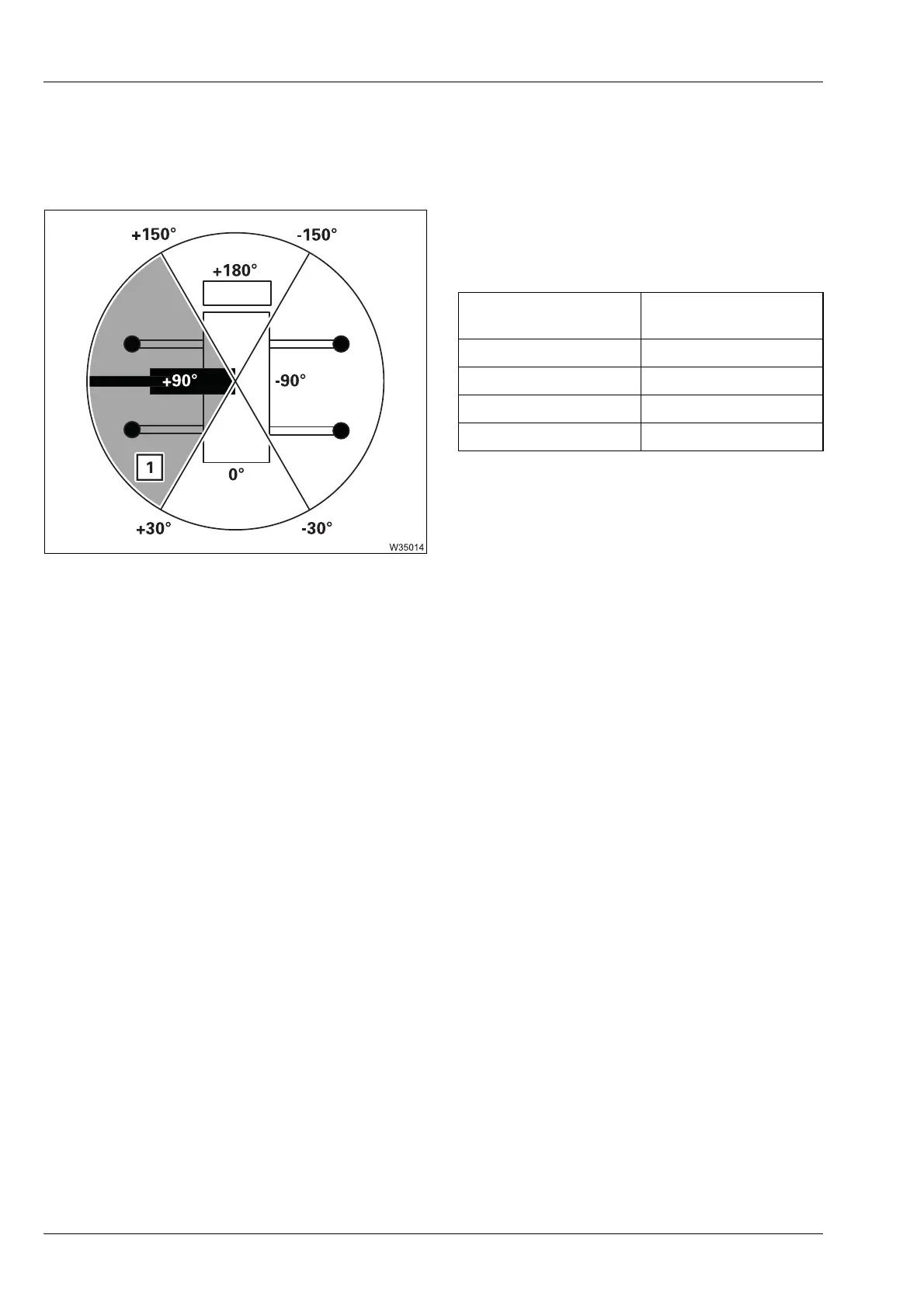
The specified lifting capacities are only enabled for specific slewing ranges.
The
lifting capacity table contains a direction
specification for the enabled slewing range,
which is assigned to a superstructure position.
This superstructure position is the starting
point for the enabled slewing range. A com-
plete turn is always divided in four slewing
ranges. The size of the slewing range is
defined via an angular region around the start-
ing point, e.g. ±60° for the slewing range (1).
This results in the enabled slewing range (1)
between the slewing angles of +30° to +150°.
The size of the enabled slewing range depends on the rigged outrigger
span. The smallest respective individual width of an outrigger beam is taken
into account.
Positional
reference
Superstructure
position
Backwards 0°
To the right -90°
Forwards +180°
To the left +90°

 Loading...


