5-30 Published 3-23-2020, Control # 654-04
SET-UP AND INSTALLATION GRT655/655L OPERATOR MANUAL
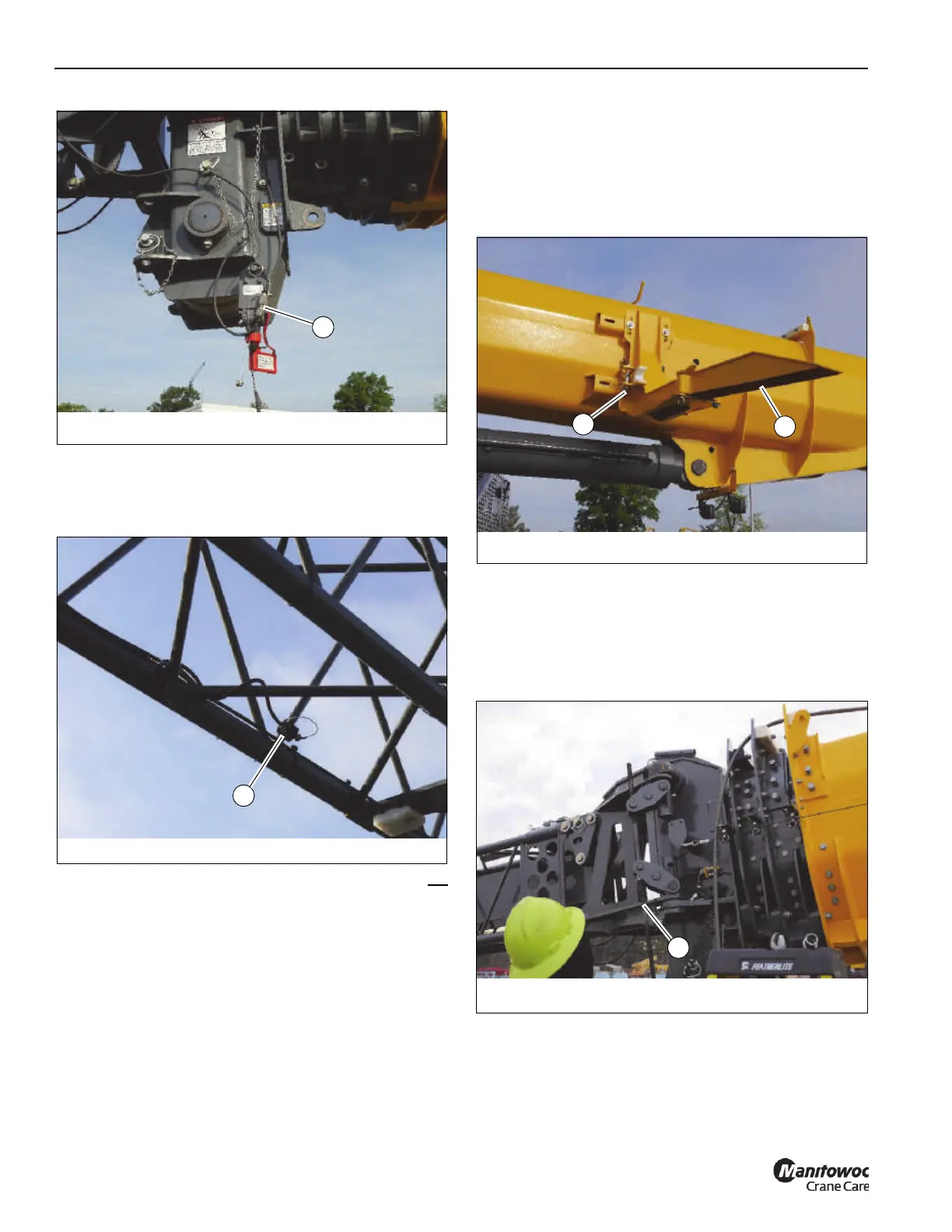
b. Wrap the boom extension anti-two block cable
around the boom extension lacing, then secure the
anti-two block cable end connector in the stowage
clip (1, Figure 5-28)
c. If the boom extension stinger section was not
erected, disconnect the boom extension base
section anti-two block cable end connector from the
anti-two block switch at the nose of the boom
extension stinger section. Stow the cable end
connector in the stowage clip.
Connect the boom extension stinger section
anti-two block cable end connector to the anti-two
block switch.
6. Attach a tag line to the boom extension tip.
7. Raise the boom to horizontal.
8. Make sure the attachment pin (2, Figure 5-29) that
secures the boom extension to the rear stowage bracket
is in the stowed position and that the rear stowage ramp
(1) is folded out and locked in position.
9. Disengage the attachment pins securing the left side of
the boom extension to the boom nose.
Use an impact wrench and the provided extension
(80104116) and socket (80104383) to turn the jack
screw (1, Figure 5-30) clockwise. Make sure the
attachment pins are fully disengaged.

 Loading...


