INTRODUCTION RT9150E OPERATOR MANUAL
1-2
Published 2-23-2017, Control # 644-00
issues. They have the facilities, parts, factory trained
personnel, and the information to assist you in a timely
manner. We request that you first contact them for
assistance. If you feel you need factory assistance, please
ask the distributor’s service management to coordinate the
contact on your behalf.
New Owners
If you are the new owner of a Grove crane, please register it
with Manitowoc Crane Care so we have the ability to contact
you if the need arises.
Go to: http://www.manitowoccranes.com/MCG_CARE/
Includes/EN/changeofownership.cfm and complete the form.
Safety Information
A Safety CD which includes sections on operation, safety
and maintenance for crane operators and owners is supplied
when the crane is purchased new. Additional copies are
available from your local distributor.
General Crane Design
The Grove crane has been designed for maximum
performance with minimum maintenance. With proper care,
years of trouble-free service can be expected.
Constant improvement and engineering progress makes it
necessary that we reserve the right to make specification
and equipment changes without notice.
Specific Crane Description
The crane incorporates an all welded steel frame, using
planetary drive axles to provide four-wheel drive. Axle
steering is accomplished utilizing hydraulic steer cylinders.
The engine is mounted at the rear of the crane and provides
motive power through a six speed forward and three speed
reverse transmission. Hydraulic, double box, sliding beam
outriggers are removable.
The carrier frame incorporates an integral fifth wheel, to
which the rear axle is mounted, to provide axle oscillation.
Axle oscillation lockout is automatic when the superstructure
rotates from the travel position.
The superstructure is capable of 360° rotation in either
direction. All crane functions are controlled from the fully-
enclosed cab mounted on the superstructure.
The crane is equipped with a six-section, pinned boom.
Additional reach is obtained by utilizing an optional
swingaway boom extension. Lifting is provided by a main
and auxiliary hoists.
Lifting Capacities (Load Chart)
Lift Capacities are listed on the Load Chart in the cab.
Basic Components
For basic crane component locations, see Figure 1-2.
Axle Weight Distribution
For axle weight distribution, see Table 1-1.
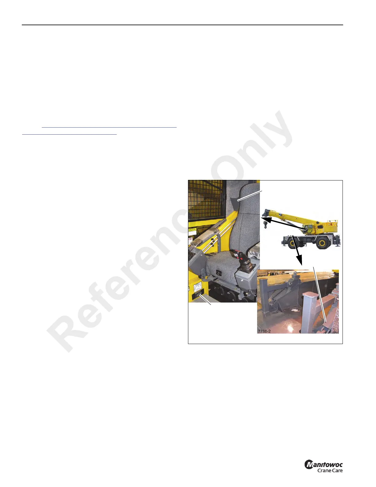
Serial Number Location
See Figure 1-1 for your crane’s serial number location:
stamped on left side of front frame (1), on the manual in the
cab (2), and inside the cab in front of the seat on the right
side (3).
Transportation and Lifting Data
Transportation and lifting information is located on the
hydraulic tank on the right side of the crane. For more
information refer to Figure 1-2.
Reference Only

 Loading...


