SET-UP AND INSTALLATION RT9150E OPERATOR MANUAL
4-32
Published 2-23-2017, Control # 644-00
Extension Electrical Connections
To connect the anti-two block (A2B) switch, aircraft warning
light or anemometer to boom extensions the following
procedures must be performed.
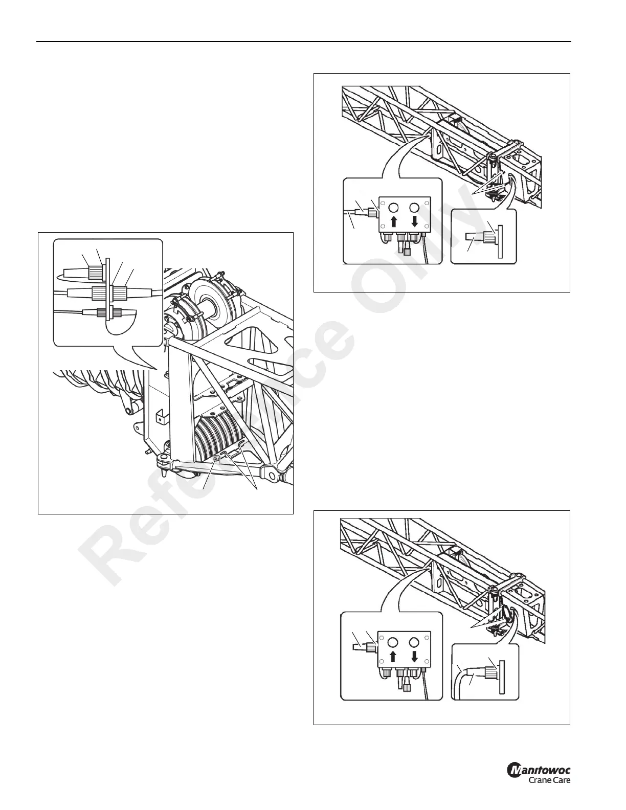
36 ft (11m) Extension Electrical Connections
The following procedure connects the 36 ft extension wiring
to the main boom circuits. This connection must be made in
order to connect the 59 ft extension wiring and to connect to
an anti-two block switch.
1. Remove the bridging plug (1) from socket (3) and plug it
into the storage socket (2) (Figure 4-43).
2. Remove the plug (4) from the storage socket (5) and
unwind the cable from the storage location (6). Connect
the plug (4) to the socket (3).
This connects the extension to the main boom circuit.
3. Wind the cable around the storage location (6) such that
it will not be damaged during crane operation.
59 ft (18 m) Extension Electrical Connections
The following procedure connects the 23 ft (7 m) extension
wiring to the 36 ft (11 m) extension wiring for operation of the
59 ft (18 m) extension. This connection must be made in
order to connect any electrical devices and an anti-two block
switch.
1. Remove the bridging plug (5) (Figure 4-44) from the
socket (1).
2. Unwind the cable (3) from the storage location (6).
3. Remove the plug (2) from the storage socket (4) and
unwind the cable (3) from the storage location (6).
Connect plug (2) into the socket (1).
This makes the connection from the 23 ft (7 m)
extension to the 36 ft (11 m) extension for use of the 59 ft
(18 m) extension.
4. Plug the bridging plug (5) into the storage socket (4).
5. Wind the cable (3) on the storage location (6) so that it
will not become damaged.
Disconnect Electrical Connections to the 59 ft (18 m)
Section
FIGURE 4-43
7567-71
1
2
3
4
5
6
7567-72
.
Reference Only

 Loading...


