4-17
RT9150E OPERATOR MANUAL SET-UP AND INSTALLATION
Published 2-23-2017, Control # 644-00
4. Connect sling assemblies to the 16,705 kg (36,825 lb)
cast counterweight using the installation lifting holes
(Figure 4-15).
5. Lift and place the counterweight onto the support
bracket on the ground.
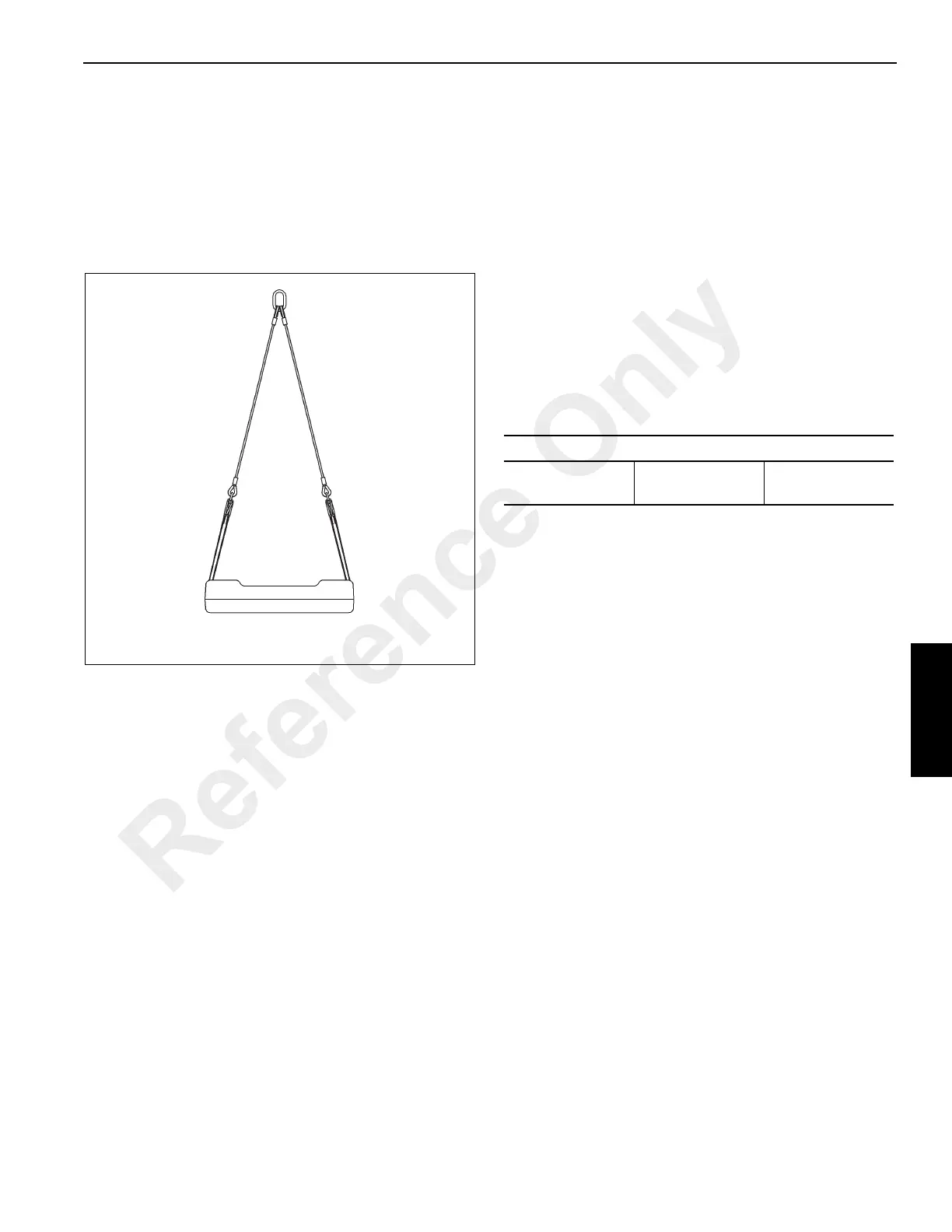
6. Connect sling assembly to the 10,902 kg (24,035 lb)
cast counterweight insert using the lifting lugs on the
insert (Figure 4-17).
7. Lift and place the counterweight insert into the 16,705 kg
(36,825 lb) cast counterweight.
8. Connect sling assembly to the heavy cast counterweight
assembly using the support bracket lifting eyes
(Figure 4-16).
9. Lift and place the counterweight assembly onto the
carrier stands.
10. Swing turntable to place the boom over the rear of the
crane.
11. Set the turntable lock pin in the down position.
12. Using the ECOS display lower the counterweight
cylinders into the tubes in the counterweight, refer to
RCL Main Menu, page 3-75.
13. Rotate the cylinders to lock into the counterweight.
14. Raise the counterweight until the display indicates the
counterweight is pre-tensioned.
15. Using the ECOS display, extend the locking cylinders
until the display indicates the counterweight is locked in
place.
Heavy Cast Counterweight Removal
1. Rig the crane with five parts of line.
2. The heavy 63,000 lb (28,576 kg) cast counterweight
assembly may be lifted in one of the following boom
configurations.
3. Enter RCL code 1100. Refer to RCL Main Menu, page 3-
75.
4. Swing turntable to place the counterweight over the front
of the crane.
5. Set the turntable lock pin in the down position.
6. Using the ECOS display, retract the locking cylinders
until the display indicates the cylinders are fully
retracted.
7. Lower the counterweight until the display indicates the
counterweight is fully lowered onto the stands.
8. Rotate the cylinders to unlock from the counterweight.
9. Raise the counterweight cylinders from the tubes in the
counterweight.
10. Connect sling assembly to the heavy cast counterweight
assembly using the lifting eyes.
11. Lift and remove the counterweight from the carrier
stands.
12. Place the counterweight on the ground.
13. Disassemble the counterweight, if necessary.
FIGURE 4-17
10,902 kg (24,035 lb) Cast Counterweight Insert
8162-3
Boom Configuration
0-0-0-0-0
0-0-0-0-50
(20 ft radius)
0-0-0-50-0
Reference Only

 Loading...


