4-21
RT9150E OPERATOR MANUAL SET-UP AND INSTALLATION
Published 2-23-2017, Control # 644-00
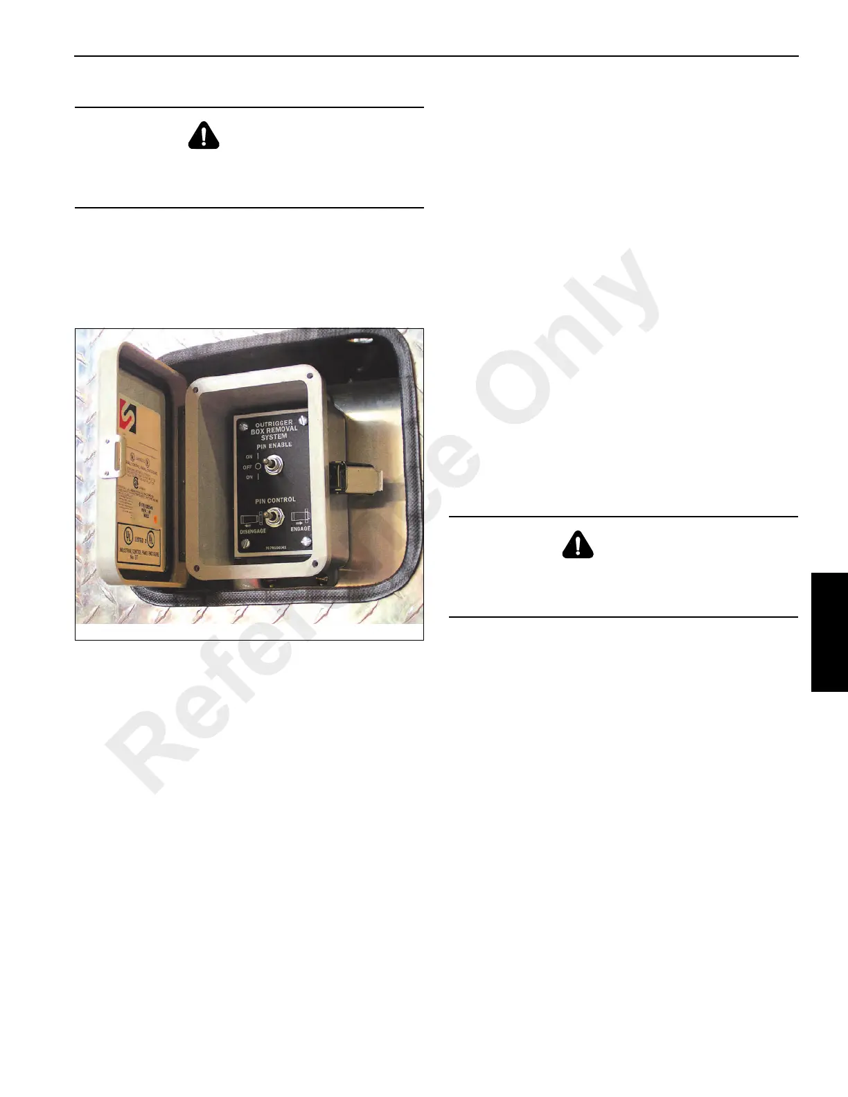
4. Using the appropriate outrigger box removal control:
either in the left front fender for the front outrigger box or
in the right rear fender for the rear outrigger box, hold the
Pin Enable switch to the ON position (Figure 4-22) and
push the Pin Control switch to DISENGAGE until the
pinning cylinder rods are fully retracted.
5. Disconnect the carrier external electrical connector from
the outrigger external connection.
6. Disconnect the carrier hydraulic quick disconnects from
the external connections of the outrigger. Stow the
carrier lines inside the fender.
7. Lift the outrigger box from the carrier.
8. Stow the retainer pins in the stowage clamps on the
outrigger box.
9. Stow the electrical connector in the plug provided on the
fender.
Outrigger Box Installation
NOTE: Outrigger boxes are not interchangeable front to
rear or with outrigger boxes from another crane.
The outrigger box assembly weighs approximately
9427 lb (4276 kg).
1. Make sure the outrigger pressure bleed valve is closed.
2. Connect sling assembly to the lifting lugs provided on
each end of the outrigger box (Figure 4-21).
3. Lift and align the outrigger box close to the installed
position at the rear or front of the carrier, as applicable.
4. Connect the carrier external electrical connector to the
outrigger external connection.
5. Install the carrier hydraulic quick disconnects to the
external connections of the outrigger box.
6. Lower the outrigger box aligning the pinning cylinder
pins with the attach points on the carrier frame.
7. Using the appropriate remote mounted pin control box,
hold the Pin Enable switch at the ON position and hold
the Pin Control switch to the ENGAGE position
(Figure 4-22).
8. After the pinning cylinders have fully engaged the
outrigger box, install a quick release pin in the end of
each of the cylinder rod ends (1) (Figure 4-20).
CAUTION!
Do not activate any switches on the control in
(Figure 4-22) until you are thoroughly familiar with the
outrigger box installation and removal procedure.
CAUTION!
Do not activate any switches on the control (Figure 4-22)
until you are thoroughly familiar with the outrigger box
installation and removal procedure.
Reference Only

 Loading...


