4-35
RT9150E OPERATOR MANUAL SET-UP AND INSTALLATION
Published 2-23-2017, Control # 644-00
Position for Main Boom Operation
The locking device on the hose drum must be undone:
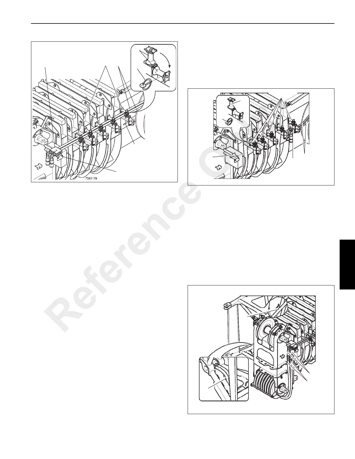
1. Loosen the hinged pins (5) (Figure 4-51) and fold up the
guide sheaves (4).
2. Detach the strain relief from the holder (3) and attach it
to the holder (2).
3. Fold down the guide sheaves (4) and secure them with
the hinged pins (5).
Establishing the Hydraulic Connection
1. If necessary, bring the connections (1) (Figure 4-52) into
the position for lattice extension operations on page 4 -
34.
2. Remove the hose line (2) from the clamp (4).
3. Feed the hose lines towards the left hand side through
the lower opening (3) in the 36 ft (11 m) section under
the boom head.
4. Remove the protective caps to the connections (1) and
attach the hose lines (observe color code).
FIGURE 4-51
7567-36
1
2
5
3
4
4
Reference Only

 Loading...


