OPERATING CONTROLS AND PROCEDURES MLC650 VPC-MAX™ OPERATOR MANUAL
3-4
Published 04-06-18, Control # 231-14
specified and make sure the proper counterweight
position column of the capacity chart is selected before
raising or lowering the boom.
• If required per the rigging drawing in use (boom and
luffing jib), make sure the intermediate suspension is
properly installed. Otherwise, damage to the boom and
jib sections can occur.
For some boom and luffing jib configurations, it is normal
for the intermediate suspension to appear slack during
boom and luffing jib raising and operation. If your
intermediate suspension appears slack —
- make sure it is installed in the proper location,
- make sure the proper pendant buttons are pinned to
the sockets,
and continue operation.
• The counterweight assembly will remain in its last
position when the engine is turned off during operation.
• Operate only with the crane on a firm surface that is
uniformly supporting:
- With load, grade must not exceed 1% in any
direction — 1 ft in 100 ft (0,3 m in 30 m).
- Without load, see Maximum Allowable Travel
Specifications Chart.
- During crane operation, the elevation outside of the
crawlers may be up to 152 mm (6 in) above the
grade of the crawlers to 610 mm (24 in) below the
grade of the crawlers. Also, the grade outside of the
crawlers shall not exceed 5% in any direction.
These conditions apply to any area the auxiliary
frame assembly will pass over.
• Prior to using the crane each day, inspect the VPC and
VPC-MAX roller paths on the rotating bed and beam for
obvious obstructions and/or signs of damage. Remove
the obstructions. Contact the Manitowoc Crane Care
Lattice Team for inspection and repair criteria.
• Do not operate the crane, to include raising the boom
from ground level, if the wind exceeds the limits given in
Capacity Charts. Monitor the wind speed in the working
screen of the crane’s RCL/RCI Display or contact your
local weather station. See Wind Conditions in the
Capacity Chart Manual.
• Be aware of increased tail swing with the VPC-MAX
counterweight assembly. The counterweight assembly
can strike objects or personnel in the area of the travel
and swing paths.
• Warn all personnel to stand well clear of the crane. The
VPC-MAX counterweight assembly extends and retracts
automatically without warning — it can strike personnel.
Anytime the VPC-MAX counterweight assembly moves,
an audible alarm will sound and the amber lights on the
counterweight tray and beam will flash to warn
personnel to stay clear.
• Provide a signal person for all crane operations.
Have signal person watch for clearance behind and
under the counterweight assembly while swinging and
traveling. Do not allow the counterweight to strike
obstructions or contact the foundation.
Depending on lifted load, clearance under the auxiliary
frame assembly will vary from 254 mm (10 in) to 1,5 m
(5 ft).
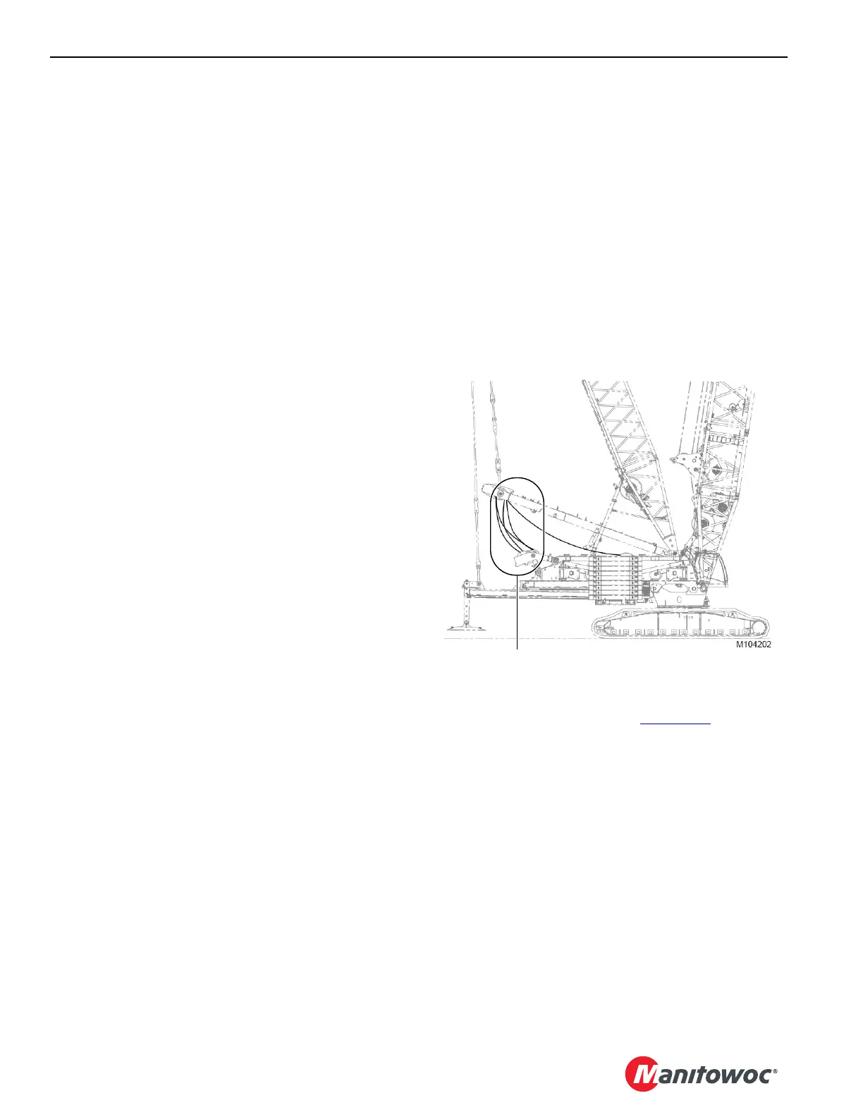
• During operation, it is normal for the live mast wire rope
reeving to become slack (Figure 3-1
) when the
counterweight tray is at the minimum working position.
This most commonly occurs when operating at high
boom angles with light loads.
When this condition occurs, the VPC-MAX beam will be
supported by the beam hooks resting on the rotating bed
pins.
• When the crane is left unattended, park it as instructed in
Section 3 of Crane Operator Manual. If the boom cannot
be lowered to the ground, position it at the mid-point of
the boom angle range given in the Capacity Chart.
FIGURE 3-1
Slack Here is Normal

 Loading...


