Manitowoc Published 04-06-18, Control # 231-14 4-33
MLC650 VPC-MAX™ OPERATOR MANUAL SET-UP AND INSTALLATION
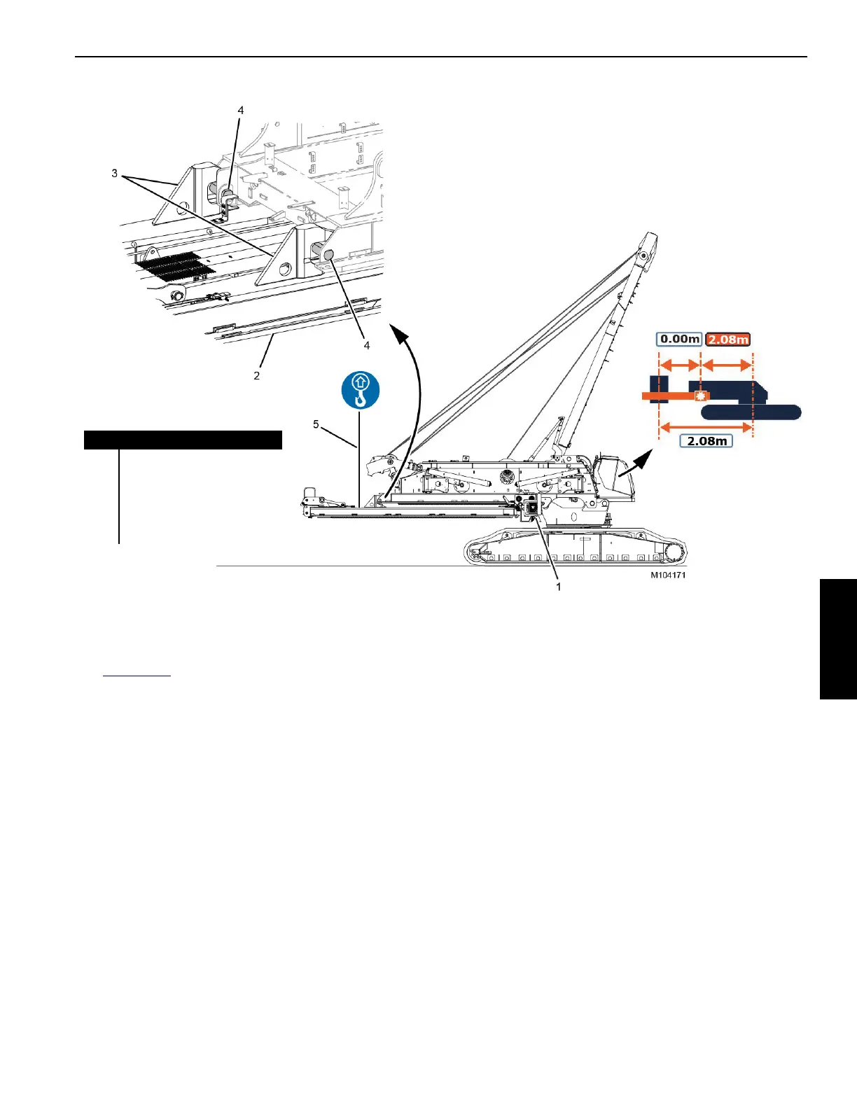
See Figure 4-32 for the following procedure.
7. Stop moving the actuator (1) forward when it is at the
minimum working position:
- The VPC-MAX calibration screen in the cab should
read 2.08 as shown in View A.
- The VPC-MAX
beam hooks (1, View B) should be
positioned directly over the pins (2) at the rear of the
rotating bed.
8. Adjust the beam-on-hook limit switches as instructed in
Section 6 of this manual.
9. Adjust the beam up limit switches as instructed in
Section 6 of this manual.
10. Slowly lower the beam with the assist crane until the
hooks (3) are resting on the pins (4), thereby supporting
the beam.
NOTE: The beam will trip the two beam-on-hook limit
switches when the hooks rest on the pins. In this
state, the control system does not allow the
actuator to travel.
11. Slowly lower the assist crane hook to slacken pendants
(5).
12. Unpin the pendants from the beam.
Item Description
1Actuator
2 VPC-MAX Beam
3 Hook (qty 2)
4Pin (qty 2)
5 Pendants from Assist Crane
FIGURE 4-32
View A
View B

 Loading...


