6-5
6.3.1 Flow Calibration (User)
6.3.1.1 Principles
A new flow sensor must be calibrated.
The measurement accuracy of flow sensors may be affected by the operating
environment, especially when they have been used for a long time, and the tidal
volume control may also experience a great deviation correspondingly.
After-sales engineers can call users to help them resolve the deviation problem
through calibration.
Before calibration, perform the auto circuit leak test and ensure that no leak
exists.
During calibration, ensure that the drive gas pressure is within the specified
range. Otherwise, the calibration may fail.
Set the machine to work in EFCS mode for flow calibration.
This calibration item is used to calibrate only the flow sensors and inspiratory valve in the circuit.
The built-in flow measurement base source of the machine is utilized to calibrate the inspiratory
flow sensor, expiratory flow sensor, and inspiratory valve in the breathing system. The VCM
opens the inspiratory valve based on inspiratory valve DA values obtained from service
calibration, to inflate the circuit of the breathing system, records the flow of the built-in flow
sensor, uses the measured value of the built-in flow sensor as well as AD values collected by the
inspiratory flow sensor and expiratory flow sensor as the data of one calibration point for flow
sensors, and uses the measured value of the built-in flow sensor as well as the DA value of the
inspiratory valve as the data of one calibration point for the inspiratory valve. Change the DA
value of the inspiratory valve to obtain calibration data under a series of flows, forming a flow
calibration data table. The flow should be in the range from 0 L/min to 120 L/min when the
inspiratory valve is opened during flow calibration.
If the inspiratory flow sensor and expiratory flow sensor have been used for months, for example,
three months after calibration, the measured tidal volume greatly deviates from the settings (with
the deviation of more than 9%) due to sensor aging or environmental factors; or a flow sensor is
replaced. In this case, the flow sensor needs to be calibrated. The flow calibration (user) can be
adopted.
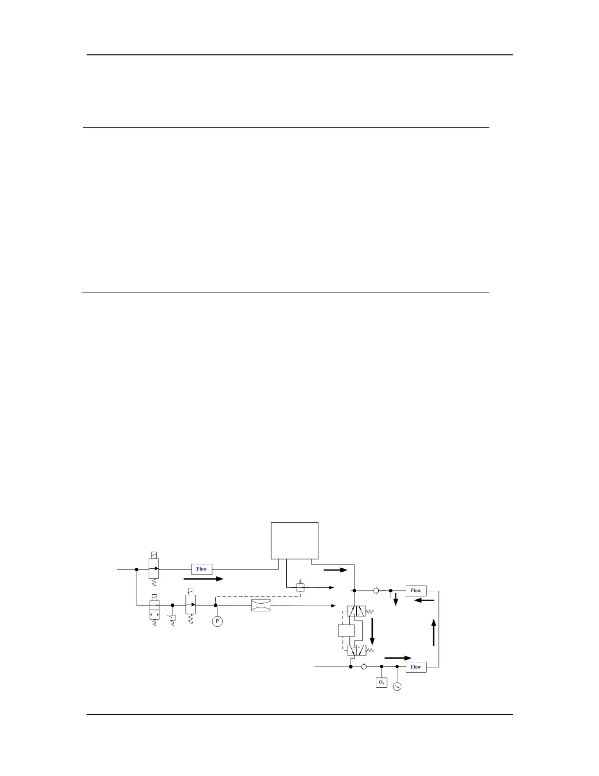
Figure 1 Schematic diagram of flow calibration (user)
safety
valve
valve
sensor
water
collection cup
flow sensor
 Loading...