8-12
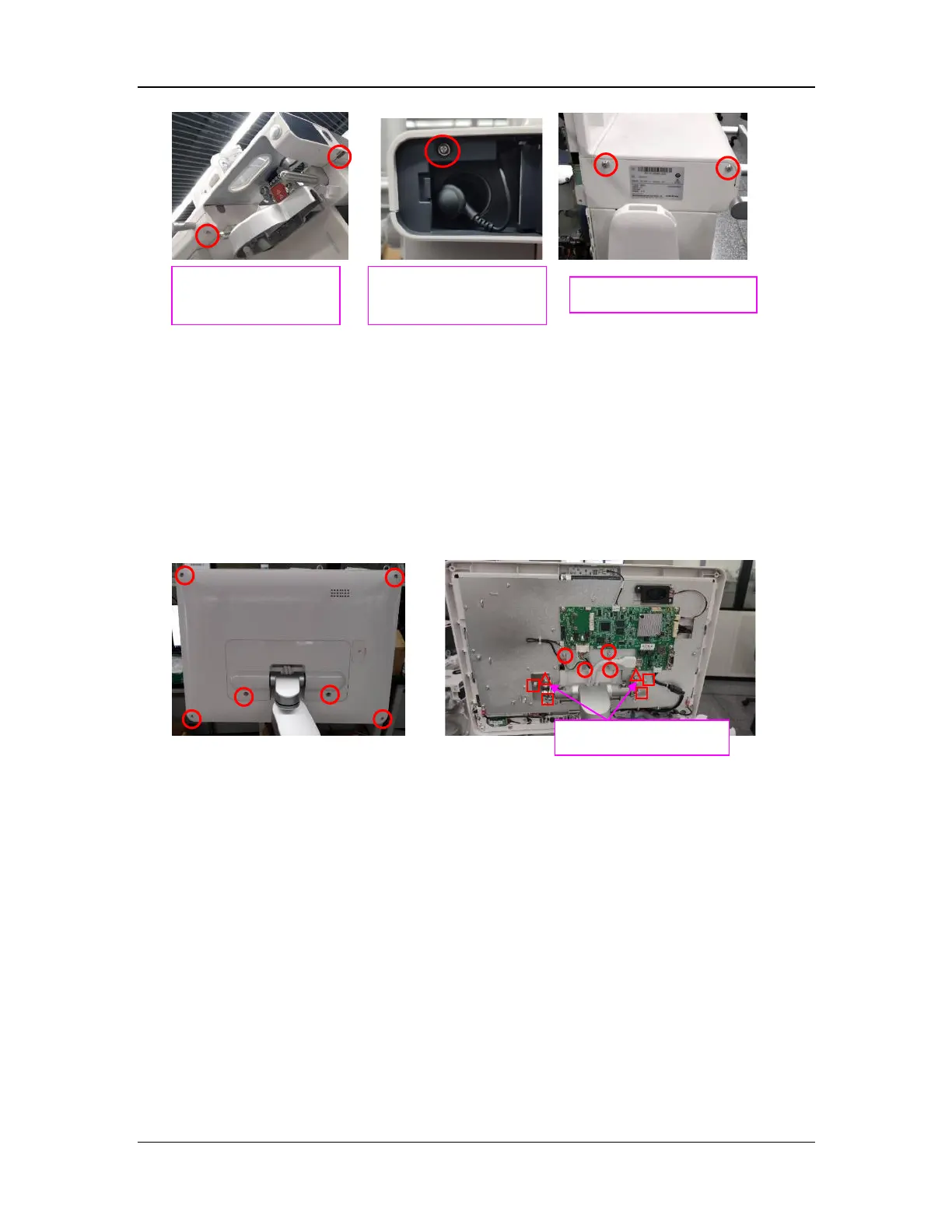
8.13.7 Remove the Display Assembly
1. Remove the six screws (marked by ○ in Figure A) with the Phillips screwdriver to remove
the rear cover plate of the display assembly.
2. Remove the four screws (marked by ○ in Figure B) fastening the cable with the Phillips
screwdriver to remove the cable.
3. Pre-loosen the two screws (marked by △ in Figure B) with the Phillips screwdriver and turn
them counterclockwise three or four rounds. Then remove the four screws (marked by □ in
Figure B). Finally, vertically lift the display assembly up to remove it.
Figure A Figure B
8.14 Disassemble the N2O, Air, and O2 Inlet Assemblies
8.14.1 Prepare for Disassembly
8.14.1.1 Tools
During parts disassembly and replacement, the following tools may be required:
M4 hexagon screw spanner
Phillips screwdriver
8.14.1.2 Preparations
Before disassembly,
Make sure that the anesthesia machine is turned off and disconnected from the A/C power
source.
Bleed down the gas pressure inside the anesthesia machine to avoid personal injury or
equipment damage.
patient circuit
O2 cell door
 Loading...