7 SAFETY RESPONSE TIME AND SAFE STOPPING DISTANCE
7-90 How to Calculate a Stopping Distance
7.2 How to Calculate a Stopping Distance
Assuming that the power supply to the robot controller is shut off during operation or that an error triggers the SS1
function, the maximum stopping distance in the worst scenario can be approximated by the following formula.
(Assume that the robot has brakes on all the axes.)
Maximum stopping distance
Dmax = (Vmax × Trin) + (0.5 × Vmax × Tmax × α)
Dmax: Maximum stopping distance
Vmax: Maximum speed (Equivalent to the SLS monitoring speed when the SLS function is enabled)
Trin: Response time (time from error detection to stop)
Tmax: Maximum stopping time (Differs from robot to robot, see chapter 7.3 )
α: Safety factor (1 or more)
The stopping time is affected by how the robot system is configured, the condition of the
robot, and its posture. Therefore, the stopping distance calculated from this formula is
approximate.
Use measurements from the system you are using to acquire an accurate stopping
distance.
Depending on the posture of the robot, the arm may droop if the axis does not have a
brake. The amount of droop is not considered in the calculation of the stopping distance
described in this section.
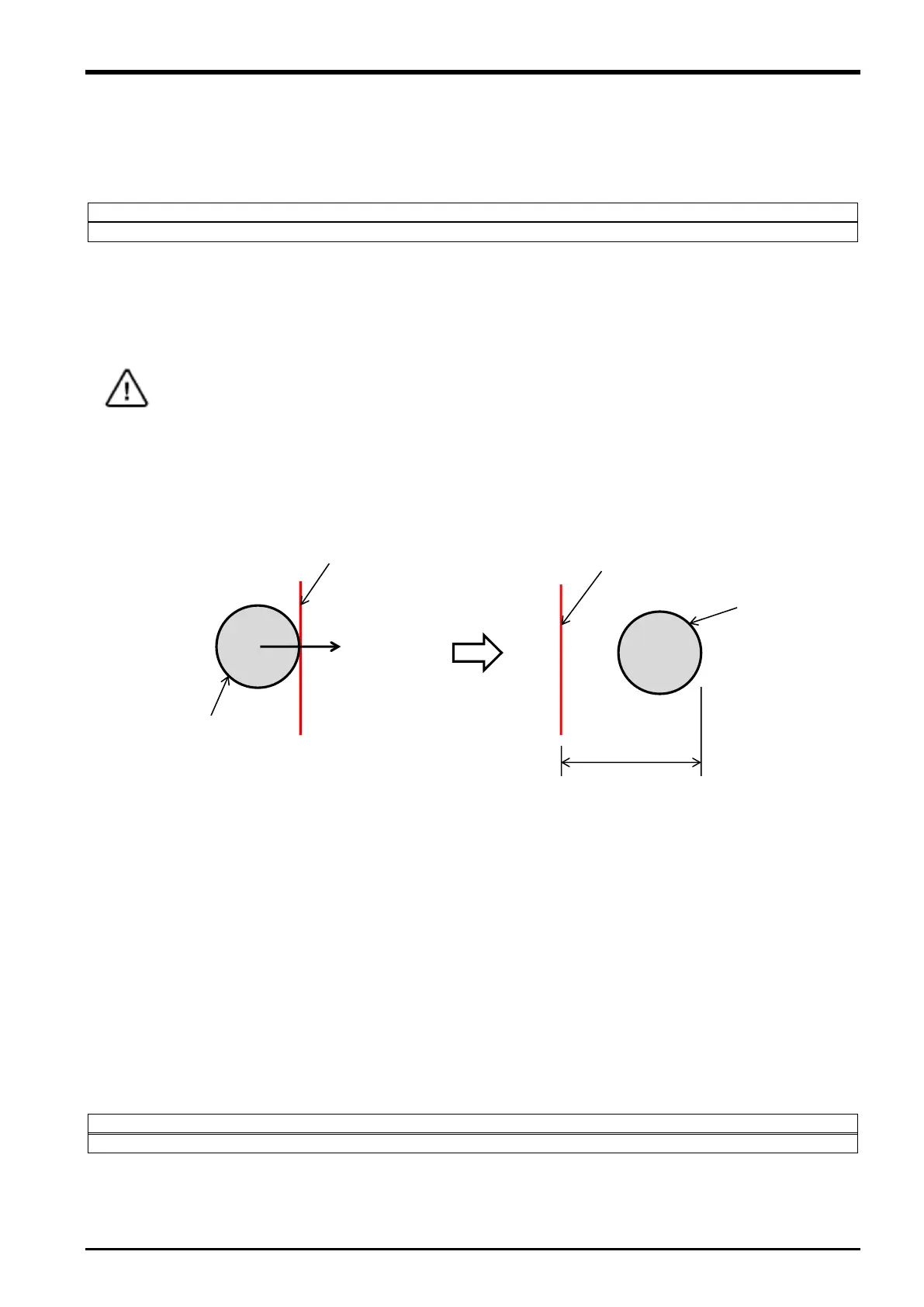
position monitoring plane
Dmax
position monitoring plane
TCP movement
Safety sphere
Safety sphere
Deceleration start Robot stop
Vmax
<Maximum speed>
When the safely-limited speed function (SLS) is enabled, detection of a speed exceeding the SLS monitoring
speed causes the SS1 function to immediately stops the robot. Therefore, the SLS monitoring speed can be
considered equivalent to the maximum speed. Thus, reducing the SLS monitoring speed enables shortening the
maximum stopping distance when power supply shut-off or an internal error shuts off the driving energy.
When Advanced Mode of the SLS function is configured, each of the X, Y, Z components are monitored for their
speed, which enables restricting the maximum stopping distances for each of the X, Y, Z components. For
example, if there is a safeguarded space in +X direction and the other directions are covered with safety fences,
reducing the SLS speed only in +X direction enables ensuring safety and minimizing impact on tact time.
<Reaction time>
Calculate the response time (Trin) from when the safety input device detects an error until when the robot starts
to decelerate as follows.
Trin = DTin + DTtrs + Trrc
DTin: Input device response time (Check the specifications of the input device.)
DTtrs: Safety data transmission time (maximum value) (Refer to "7.1 Safety Response Time".)
Trrc: Robot controller response time (delay time from when the robot controller detects an error and the SS1
command is enabled until when the robot starts to decelerate: 7.11 [ms])
Caution
 Loading...