1 FUNCTIONS AND CONFIGURATION
System Configuration 1-3
1.3 System Configuration
Fig. 1-1 shows a system architecture. This function allows the CR800-R/CR860-R controllers to perform safety
communication with the safety programmable controller (MELSEC iQ-R series safety CPU module) using the
master/local module. Using safety programmable controllers enables to perform safety communication with safety
remote I/O modules and other equipment. This helps construct safety systems. For information on the usage and
specifications of the MELSEC iQ-R, refer to the manuals shown below.
□ MELSEC iQ-R CPU Module User's Manual (Startup) (SH-081263ENG)
□ MELSEC iQ-R CPU Module User's Manual (Application) (SH-081264ENG)
□ MELSEC iQ-R CC-Link IE TSN User's Manual (Startup) (SH-082127ENG)
□ MELSEC iQ-R CC-Link IE TSN User's Manual (Application) (SH-082129ENG)
Fig. 1-1: System architecture (example)
PC
<4>RT ToolBox3
<5>GX Works3
USB, Ethernet
Safety programmable controller (master station)
Programmable controller (local station)
<1>Safety CPU module
<6>Programmable controller CPU module
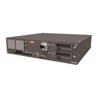
<7>Robot CPU module 1
<7>Robot CPU module 2
<7>Robot CPU module 3
<8>
Master/local
module
<2>Safety function module
<3>
Master/local
module
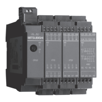
Safety remote I/O module
(remote station)
CC-Link IE TSN device
CC-Link IE TSN
(Ethernet cable)
Laser scanner
Status indicator
light
Light curtain
CC-Link IE TSN device
CC-Link IE TSN
(Ethernet cable)
SSCNET III/H
(SSCNET III optical cable)
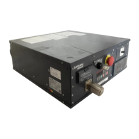
<9>Controller
<9>Controller
<9>Controller
I/O
Emergency stop switch
Door switch
Mode selector switch
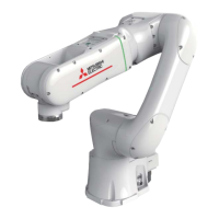
<10>Robot arm
<10>Robot arm
<10>Robot arm

 Loading...
