95
Selection and protection of a motor
4
PARAMETERS
4.8 Selection and protection of a motor
4.8.1 Motor protection from overheat (Electronic thermal relay function) (Pr. 9, Pr. 51)
*1 The parameters can be set when Pr. 160 User group read selection = "0" (Refer to page 156)
*2 When parameter is read using the FR-PU04, a parameter name different from an actual parameter is displayed.
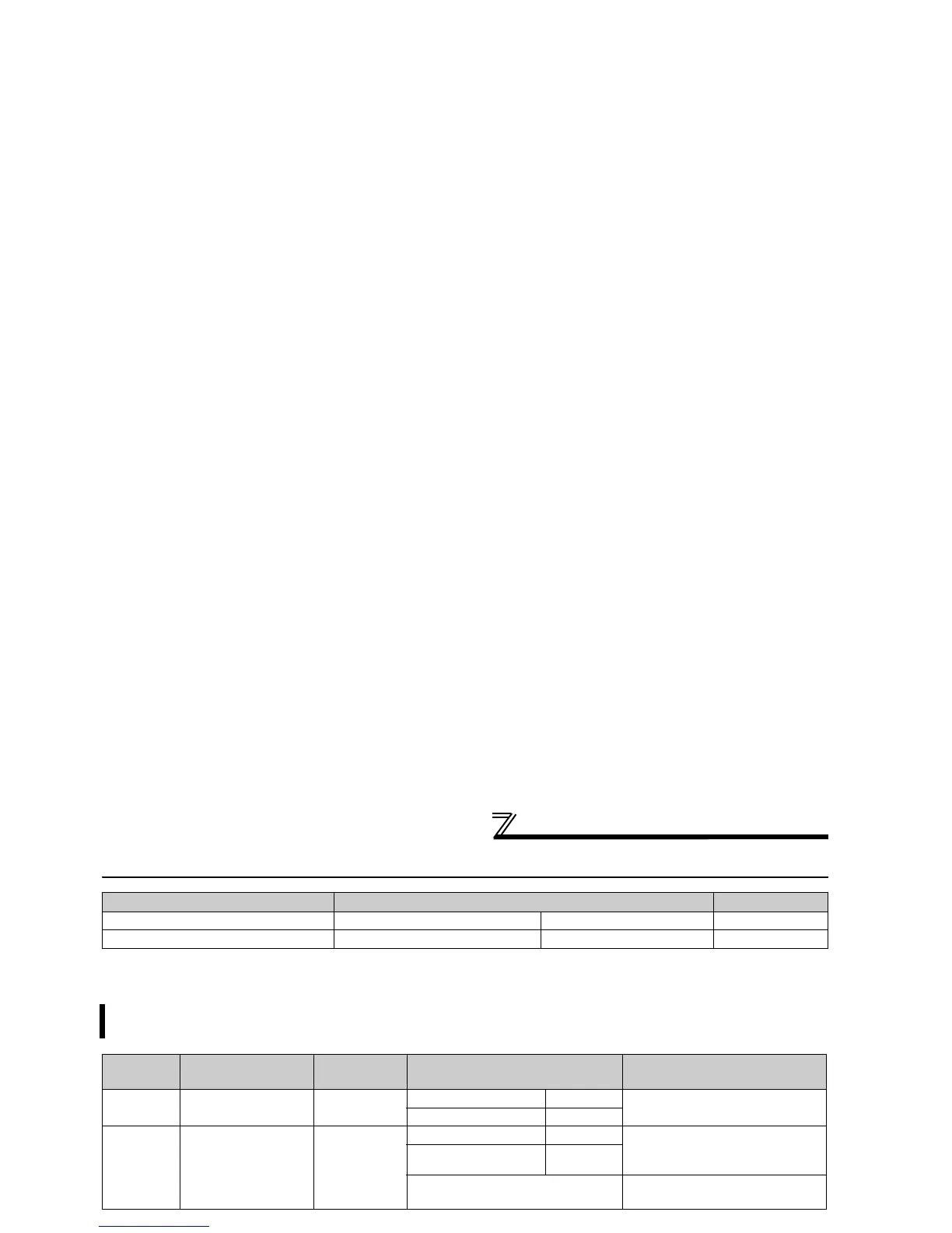
(1) Electronic thermal O/L relay (Pr. 9)
Purpose Parameter that must be Set Refer to page
Motor protection from overheat Electronic thermal O/L relay Pr. 9, Pr. 51 95
Use the constant torque motor Applied motor Pr. 71 97
Set the current of the electronic thermal O/L relay to protect the motor from overheat. This feature provides the
optimum protective characteristics, including reduced motor cooling capability, at low speed.
Parameter
Number
Name Initial Value Setting Range Description
9
Electronic thermal
O/L relay
Rated inverter
current
55K or less 0 to 500A
Set the rated motor current.
75K or more 0 to 3600A
51
*2
Second electronic
thermal O/L relay
*3
9999
55K or less 0 to 500A Made valid when the RT signal is
on.
Set the rated motor current.
75K or more 0 to 3600A
9999
Second electronic thermal O/L relay
invalid
Electronic thermal relay function operation characteristic
This function detects the overload (overheat) of the
motor, stops the operation of the inverter's output
transistor, and stops the output. (The operation
characteristic is shown on the left)
⋅ Set the rated current [A] of the motor in Pr. 9. (When
the power supply specification is 200V/220V(400V/
440V) 60Hz, set the 1.1 times the rated motor current.)
⋅ Set "0" in Pr. 9 when you do not want to activate the
electronic thermal relay function, e.g. when using an
external thermal relay with the motor. (Note that the output
transistor protection of the inverter functions (E.THT).)
⋅ When using the Mitsubishi constant-torque motor
1) Set "1"in
Pr. 71
. (This provides a 100% continuous torque
characteristic in the low-speed range.)
2) Set the rated current of the motor in Pr. 9.
*1 When a value 50% of the inverter rated output current (current
value) is set in Pr. 9
*2 The % value denotes the percentage to the inverter rated output current.
It is not the percentage to the motor rated current.
*3 When you set the electronic thermal relay function dedicated to the
Mitsubishi constant-torque motor, this characteristic curve applies
to operation at 6Hz or higher.
CAUTION
⋅ Protective function by electronic thermal relay function is reset by inverter power reset and reset signal input. Avoid
unnecessary reset and power-off.
⋅ When multiple motors are operated by a single inverter, protection cannot be provided by the electronic thermal relay function.
Install an external thermal relay to each motor.
⋅ When the difference between the inverter and motor capacities is large and the setting is small, the protective characteristics of
the electronic thermal relay function will be deteriorated. In this case, use an external thermal relay.
⋅ A special motor cannot be protected by the electronic thermal relay function. Use the external thermal relay.
⋅ The operation time of the transistor protection thermal relay shortens when the Pr. 72 PWM frequency selection setting increases.
120
Electronic thermal relay
function for transistor
protection
52.5%
105%
50
100
150
60
120
180
240
50
60
70
6Hz
20Hz
10Hz
6Hz
0.5Hz
30Hz or more*
3
20Hz
10Hz
0.5Hz
Pr. 9 = 50% setting of
inverter rating*
1.2
Pr. 9 = 100% setting
of inverter rating*
1.2
(s) unit display in this region
(min) unit display in
this region
Operation time (min)Operation time (s)
Characteristic when
electronic thermal relay
function for motor
protection is turned off
(When Pr. 9 setting is 0(A))
30Hz
or more*
3
Inverter output current(%)
(% to the rated output current)
Operation region
Region on the left of
characteristic curve
Non-operation region
Region on the left of
characteristic curve
 Loading...