20
Main circuit terminal specifications
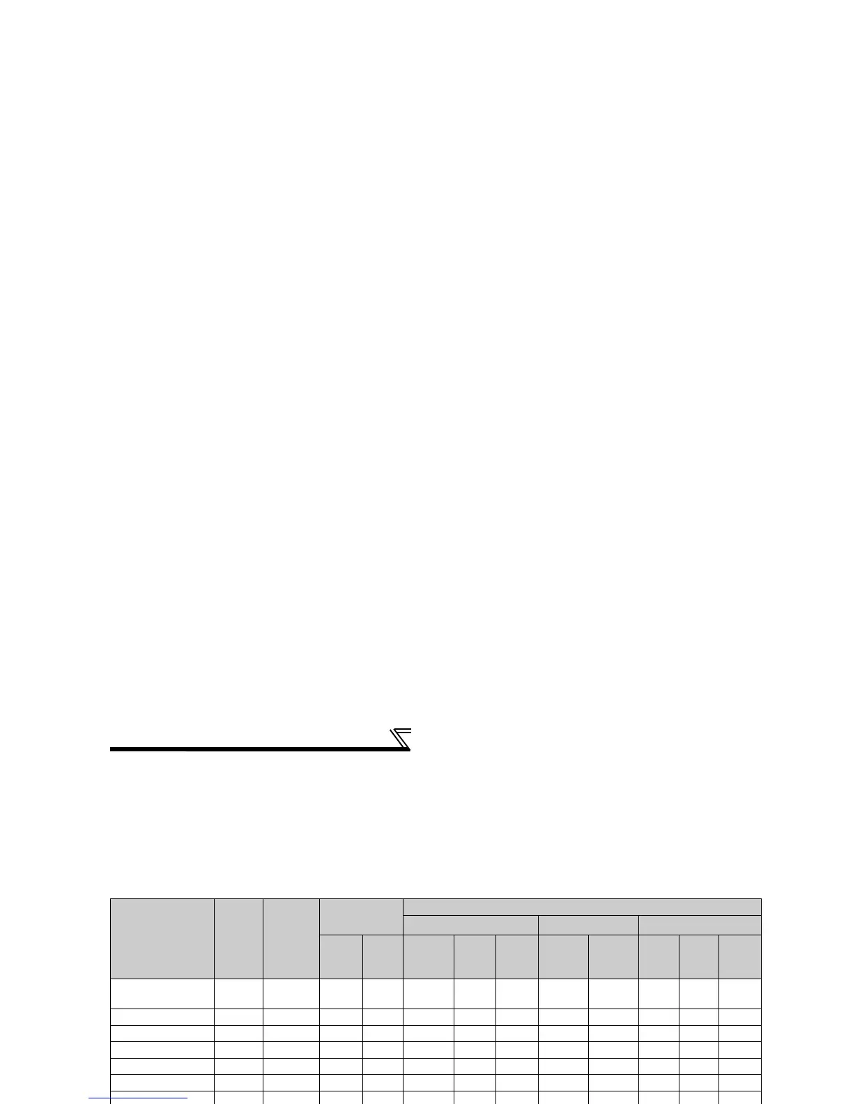
2.2.3 Cables and wiring length
(1) Applied cable size
Select the recommended cable size to ensure that a voltage drop will be 2% max.
If the wiring distance is long between the inverter and motor, a main circuit cable voltage drop will cause the motor
torque to decrease especially at the output of a low frequency.
The following table indicates a selection example for the wiring length of 20m.
200V class (when input power supply is 220V)
Applicable Inverter
Type
Terminal
Screw
Size
*4
Tightening
Torque
N·m
Crimping
Terminal
Cable Sizes
HIV, etc. (mm
2
) *1
AWG/MCM *2
PVC, etc. (mm
2
) *3
R/L1,
S/L2,
T/L3
U, V, W
R/L1,
S/L2,
T/L3
U, V, W
Earth
(Ground)
cable
R/L1,
S/L2,
T/L3
U, V, W
R/L1,
S/L2,
T/L3
U, V, W
Earth
(Ground)
cable
FR-F720-0.75K to
2.2K
M4 1.5 2-4 2-4 2 2 2 14 14 2.5 2.5 2.5
FR-F720-3.7K M4 1.5 5.5-4 5.5-4 3.5 3.5 3.5 12 12 4 4 4
FR-F720-5.5K M4 1.5 5.5-4 5.5-4 5.5 5.5 5.5 10 10 6 6 6
FR-F720-7.5K M4-M5 2.5 14-5 8-5 14 8 14 6 8 16 10 16
FR-F720-11K M4-M5 2.5 14-5 14-5 14 14 14 6 6 16 16 16
FR-F720-15K M5 2.5 22-5 22-5 22 22 14 4 6 (
*5)2525 16
FR-F720-18.5K M6 4.4 38-6 38-6 38 38 22 2 2 35 35 25
FR-F720-22K M8-M6 7.8 38-8 38-8 38 38 22 2 2 35 35 25
FR-F720-30K M8-M6 7.8 60-8 60-8 60 60 38 1/0 1/0 50 50 25
FR-F720-37K M8-M6 7.8 80-8 80-8 80 80 38 3/0 3/0 70 70 35
FR-F720-45K M10-M8 14.7 100-10 100-10 100 100 60 4/0 4/0 95 95 50
FR-F720-55K M10-M8 14.7 100-10 100-10 100 100 60 4/0 4/0 95 95 50
FR-F720-75K M12 24.5 150-12 150-12 125 125 38 MCM250 MCM250
FR-F720-90K M12 24.5 150-12 150-12 150 150 38 2×4/0 2×4/0
FR-F720-110K M12 24.5 100-12 100-12 2×100 2×100 38 2×4/0 2×4/0
*1 The cable size is that of the cable (HIV cable (600V class 2 vinyl-insulated cable) etc.) with continuous maximum permissible temperature of
75°C. Assumes that the ambient temperature is 50°C or less and the wiring distance is 20m or less.
*2 The recommended cable size is that of the cable (THHW cable) with continuous maximum permissible temperature of 75°C. Assumes that the
ambient temperature is 40°C or less and the wiring distance is 20m or less.
(Selection example for use mainly in the United States.)
*3 For the 15K or less, the recommended cable size is that of the cable (PVC cable) with continuous maximum permissible temperature of 70°C.
Assumes that the ambient temperature is 40°C or less and the wiring distance is 20m or less.
For the 18.5K or more, the recommended cable size is that of the cable (XLPE cable) with continuous maximum permissible temperature of
90°C. Assumes that the ambient temperature is 40°C or less and wiring is performed in an enclosure.
(Selection example for use mainly in Europe.)
*4 The terminal screw size indicates the terminal size for R/L1, S/L2, T/L3, U, V, W, and a screw for earthing (grounding).
For the 7.5K, 11K screw sizes are different. (<R1/L11, S1/L11, PR, PX> - <R/L1, S/L2, T/L3, U, V, W, a screw for grounding>)
For the 22K to 55K screw sizes are different. (<R/L1, S/L2, T/L3, U, V, W> - <a screw for earthing (grounding)>)
*5 When connecting the option unit to P/+, P1, N/-, use THHN cables for the option and terminals R/L1, S/L2, T/L3, U, V, W.
 Loading...