38
Connection of stand-alone option units
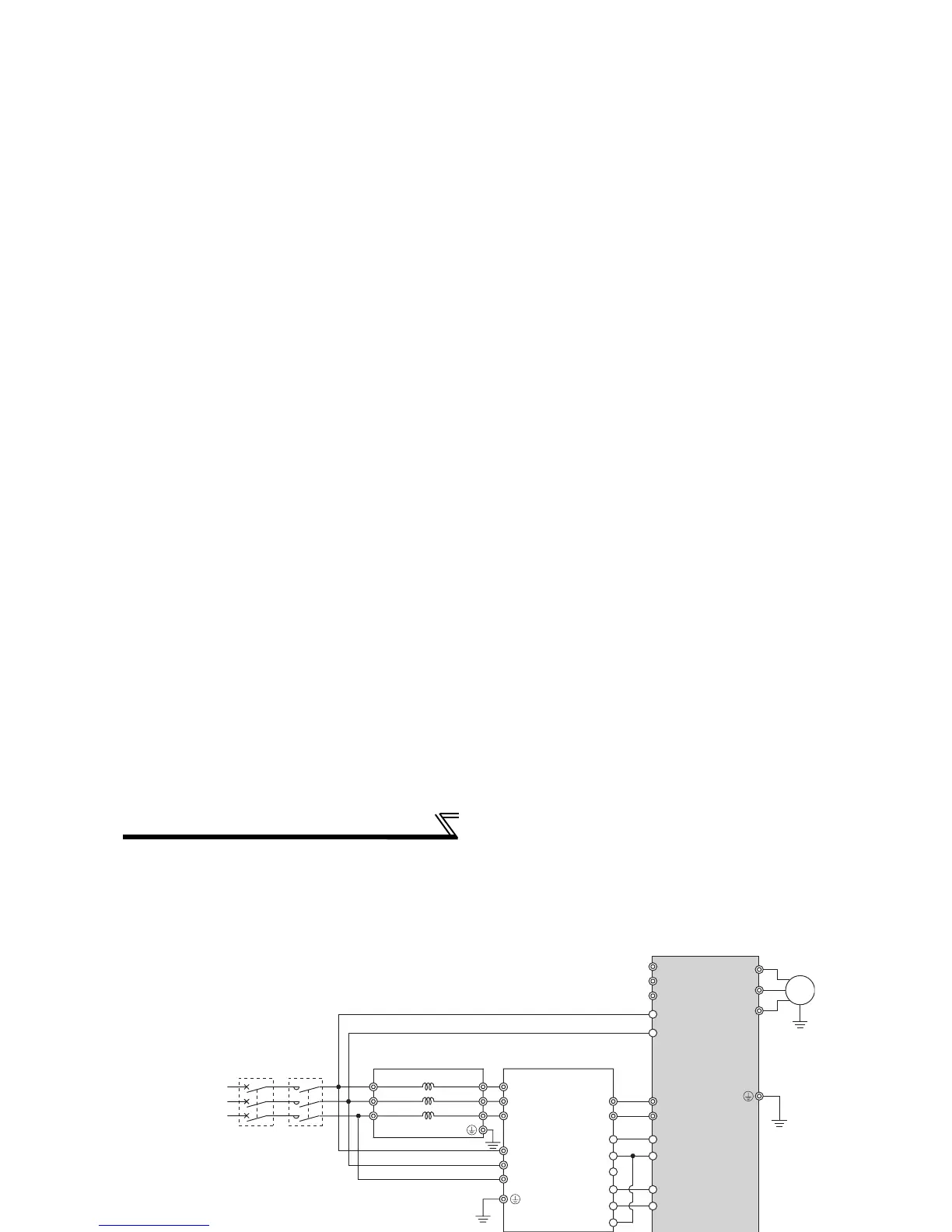
2.4.4 Connection of the power regeneration common converter (FR-CV)(55K or less)
When connecting the power regeneration common converter (FR-CV), make connection so that the inverter terminals
(P/+, N/-) and the terminal symbols of the power regeneration common converter (FR-CV) are the same.
After making sure that the wiring is correct, set "2" in Pr. 30 Regenerative function selection. (Refer to page 99.)
*1 Remove the jumpers across terminals R/L1-R1/L11 and S/L2-S1/L21 of the inverter, and connect the
control circuit power supply across terminals R1/L11-S1/L21. Always keep the power input terminals R/
L1, S/L2, T/L3 open. Incorrect connection will damage the inverter. (E.OPT (option alarm) will occur.
(Refer to page 244.))
*2 Do not insert an MCCB between the terminals P/+ − N/- (between P/L+ − P/+, between N/L- − N/-).
Opposite polarity of terminals N/-, P/+ will damage the inverter.
*3 Assign the terminal for X10 signal using any of Pr. 178 to Pr. 189 (input terminal function selection).
(Refer to page 101)
*4 Be sure to connect the power supply and terminals R/L11, S/L21, T/MC1.
Operating the inverter without connecting them will damage the power regeneration common converter.
CAUTION
⋅ The voltage phases of terminals R/L11, S/L21, T/MC1 and terminals R2/L1, S2/L2, T2/L3 must be matched.
⋅ Use sink logic (factory setting) when the FR-CV is connected. The FR-CV cannot be connected when source logic is
selected.
⋅ Do not remove a jumper across terminal P/+ and P1 except when connecting a DC reactor.
R/L11
Dedicated stand-alone
reactor (FR-CVL)
S/L21
T/L31
R2/L12
S2/L22
T2/L32
R2/L1
S2/L2
T2/L3
R/L11
S/L21
T/MC1
P/L+
U
V
W
IM
FR-CV type
Power regeneration
common converter
Inverter
PC
SD
X10 *3
RES
P24
SD
RDYB
RSO
SE
RDYA
N/L−
*2
*4
R/L1
S/L2
T/L3
R1/L11
S1/L21
P/+
N/−
*1
Three-phase
AC power
supply
MCCB
MC1
 Loading...