24
Main circuit terminal specifications
2.2.4 When connecting the control circuit and the main circuit separately
to the power supply (separate power)
• FR-F720-0.75K to 5.5K, FR-F740-0.75K to 5.5K
• FR-F720-7.5K, 11K, FR-F740-7.5K, 11K
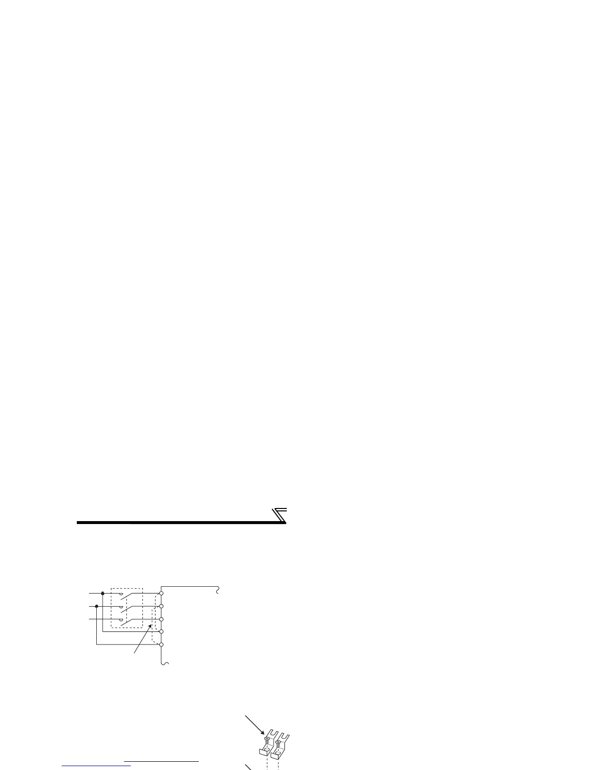
<Connection diagram> When the protected circuit is activated, opening of the electromagnetic
contactor (MC) on the inverter power supply side results in power loss in the
control circuit, disabling the alarm output signal retention. Terminals R1/L11
and S1/L21 are provided to hold an alarm signal. In this case, connect the
power supply terminals R1/L11 and S1/L21 of the control circuit to the
primary side of the MC.
1)Loosen the upper screws.
2)Remove the lower screws.
3)Remove the jumper
4)Connect the separate power
supply cable for the control
circuit to the lower terminals
(R1/L11, S1/L21).
1)Remove the upper screws.
2)Remove the lower screws.
3)Remove the jumper.
4)Connect the separate power
supply cable for the control
circuit to the upper terminals
(R1/L11, S1/L21).
Inverter
MC
R/L1
S/L2
T/L3
R1/L11
S1/L21
Remove the jumper
Main circuit terminal block
R1/L11
S1/L21
3)
1)
2)
4)
S/L2
T/L3
R1/L11
S1/L21
R/L1
3)
4)
1)
2)
Main circuit
terminal block
S1/L21
R1/L11
S/
L2
T/
L3
R/
L1
R1/L11
S1/L21
 Loading...