Control units System overview
2 - 10
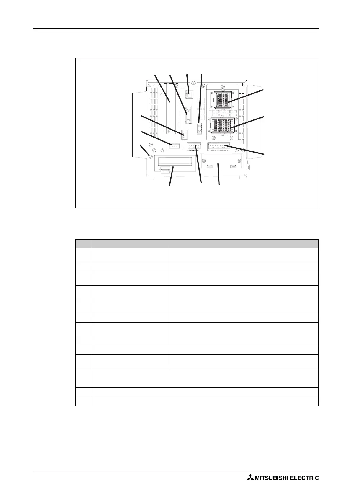
2.3.2 CR1DA components
Please install the ferrite core supplied with the unit.
R002089E
Fig. 2-9: Rear of CR1DA control unit
No. Name Function
Connection fro servo power supply
cable (CN1)
Robot power supply
Connection for signal cable (CN2) Robot control cable
Output for EMERGENCY-STOP state
(EMGOUT)
Output of current EMERGENCY-STOP state
Slot for hand interface card (HND)
Slot for installing the interface card for the pneumatically operated
gripper hand
Input for EMERGENCY-STOP push-
button (EMGIN)
Connection for EMERGENCY-STOP pushbutton or circuit
SLOT1 Slot for optional plug-in cards
Connection of a parallel input/
output ports (RIO)
Port to connect an additional parallel input/output ports
Additional stop input (SKIP) Additional robot stop
Expansion memory connection Connection for an optional memory cassette
Port or conveyor belt tracking
(CNENC)
Connection of up to 2 encoders for conveyor belt tracking
Ethernet connection (LAN1)
Port to connect an ethernet cable
For the CE-approved version, use the filter and ferrite core supplied with
the equipment.
Connection for additional axes Port for connecting an additional axes
Grounding screw (3 x) Grounding connector
Tab. 2-3: Components on the rear of the CR1DA control unit
 Loading...


