System overview Control units
SD-/SQ series 2 - 13
2.3.4 CR1QA components
The CR1QA control unit is comprised of the robot CPU Q172DRCPU and the DU1A drive unit.
Please use installing the attached ferrite core.
R001788E
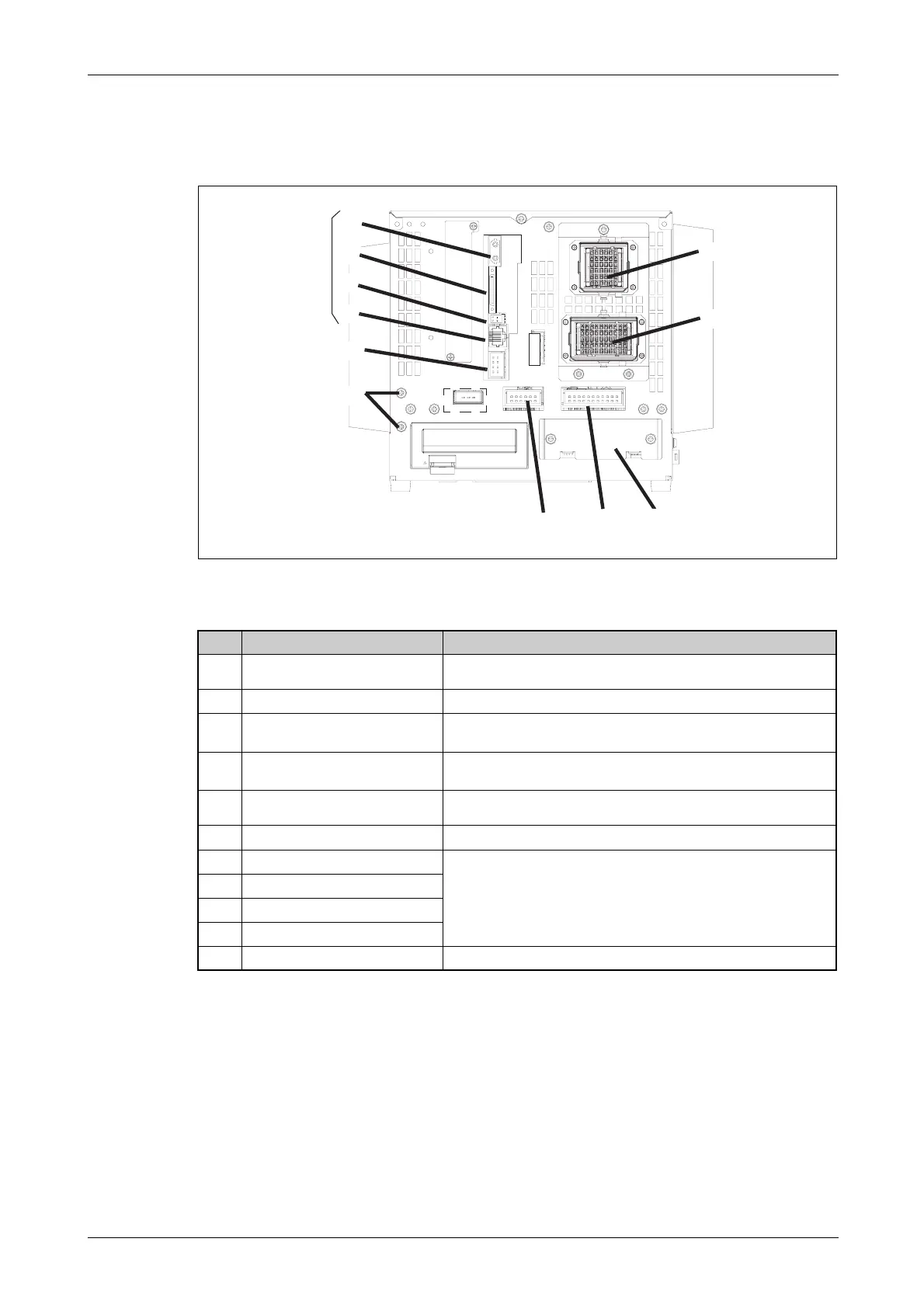
Fig. 2-11: Rear of DU1A drive unit
No. Name Function
Connection fro servo power supply
cable (CN1)
Robot power supply
Connection for signal cable (CN2) Robot control cable
Input for EMERGENCY-STOP
pushbutton (EMGIN)
Connection for EMERGENCY-STOP pushbutton or circuit
Output for EMERGENCY-STOP state
(EMGOUT)
Output of current EMERGENCY-STOP state
Slot for hand interface card (HND)
Slot for installing the interface card for the pneumatically operated
gripper hand
Additional stop input (SKIP)
Additional robot stop
OPT1A
CPU connections
CON3
DCOUT
CNDISP
Grounding terminal (3 places) The screw for grounding of the cable
Tab. 2-5: Components on the rear of the DU1A drive unit
For connection to
the robot CPU
 Loading...


