Set up the robot arm Installation
3 - 18
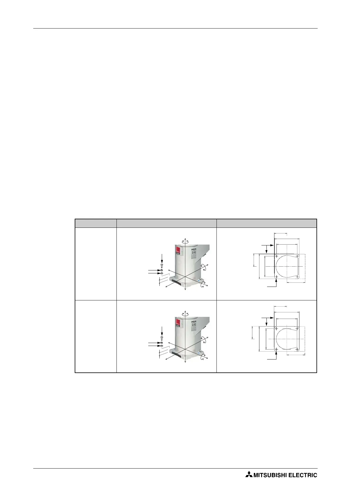
3.3.2 Set up the SCARA robot
RH-6SDH/12SDH/20SDH and RH-6SQH/12SDH/20SDH
The table below shows how to set up and fix the SCARA robots RH-6SDH/12SDH/20SDH and
RH-6SQH/12SQH/20SQH.
The base area of the robot arm has been leveled by machine.
If the bas area is too uneven then this may result in robot arm malfunctions.
Fix the robot arm above the assembly boreholes on the four outer edges of the base area using
the supplies Allen head screws.
Align the robot arm horizontally.
The average surface finish of the assembly surface should be Ra = 6.3
μ
m. If the surface is too
rough then this may result in deviations in the position of the robot arm.
To avoid position deviations, the peripheral equipment that the robot accesses as well as the robot
arm itself should be installed on a common assembly platform/area.
The base area must be designed so that no distortion can occur, even from the loads and vibrations
emanating from the robot itself.
Only remove the transport locks, suspensions and supporting brackets after setting up the robot arm.
High loads and strains occur on the base area when operating the robot at high speeds. Make
sure that the base area is suitable for the high forces and moments, as listed in Tab. 3-5.
Robot arm Fixture View from below
RH-6SDH,
RH-6SQH
R001447E R001448E
RH-12SDH/20SDH,
RH-12SQH/20SQH
R001447E R001449E
Tab. 3-4: Set up the robot arm
20
㧲
㧴
㧲
㨂
㧲
㧴
㧲
㧴
㧲
㧴
㧹
㧸
㧹
㧸
㧲
㨂
㧹
㨀
Fixing
screws (4)
M8 x 40 Allen screw
Snap ring
Washer
Installation side
(standard)
4-9 fixing boreholes
Maintenance
clearance
20
㧲
㧴
㧲
㨂
㧲
㧴
㧲
㧴
㧲
㧴
㧹
㧸
㧹
㧸
㧲
㨂
㧹
㨀
Fixing
screws (4)
M12 x 45 Allen screw
Snap ring
Washer
Installation side
(standard)
4-16 fixing boreholes
Maintenance
clearance
 Loading...


