Connection Connection of the connection cable
SD-/SQ series 4 - 3
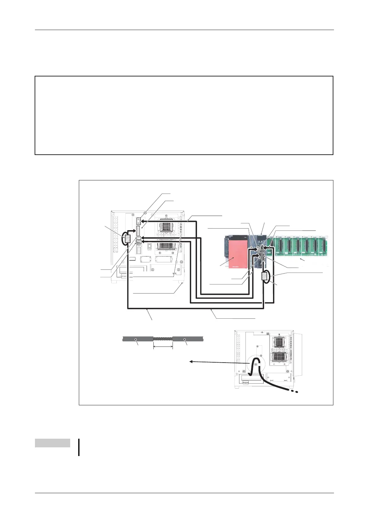
4.1.2 Connection of robot CPU to the drive unit
Connection of robot CPU Q172DRCPU to drive unit DU1A
E
ATTENTION:
● Always place the protective cap on the SSCNETIII connection when no cable is connected.
Otherwise, soiling may lead to an impairment in the transmission and to malfunctions.
● Do not remove the SSCNETIII cable as long as the power supply of the CPU system or the drive
unit is switched on.
Never look directly into the light emitted from the robot CPU or the SSCNETIII connections
of the drive unit, or into the open end of the SSCNETIII cable. The light emitted from these
complies with the IEC60825-1 standard of laser class 1 and may result in an irritation to the
eyes if viewed directly.
R001509E
Fig. 4-3: Connection of robot CPU to drive unit DU1A
NOTE
Connect the shielding of the TU cable to the grounding cable on the housing of the drive unit to
prevent electromagnetic disturbances
Remove 20 to 30 mm of wire insulation from the TU cable and
connect the shielding to the grounding terminal on the rear
of the drive unit.
Wire insulation
DU1A drive unit
Robot CPU
Q172DRCPU
Wire insulation
20–30 mm
DISP cable for robot
2Q-DISPCBL 10M
EMI cable for robot
2Q-EMICBL 10M
DCOUT
CNDISP
OPT
CON3
SSCNETIII cable
Ferrite core
CN1
SSCNETIII cable
MR-J3BUS 10M-A Ferrite core
EMI cable for robot
2Q-EMICBL 10M
EMI
Robot CPU
DISP I/F
DISP cable for robot
2Q-DISPCBL 10M
TU cable for robot
2Q-TUCBL 10M
2 ferrite cores
TU I/F
Rack
PLC power
supply
Shielding
Location of the ground terminal
TU cable for robot
2Q-TUCBL 10M
2 Ferrite cores
 Loading...


