BODY REPAIR
BASE OF BODY REPAIR
9-14
BODY REPAIR
STANDARD BODY REPAIR PROCEDURES
M4090006000031
The following is an explanation of the standard repair
procedures for the monocoque body and the frame-
type body. Furthermore, please refer to the replace-
ment of welded panels for the applicable model for
information concerning the procedures for replace-
ment of panels (as classified by position) for the vari-
ous models.
NOTE: That reference should be made to page 9-26
concerning repair procedures for the frame of frame-
type vehicles.
STANDARD PROCEDURES FOR
REPLACEMENT OF WELDED PANELS
In order to maintain the proper levels of strength,
rigidity, and precision when making welded panel
replacements, it is essential to first gain a thorough
understanding of the body structure, and then to per-
form all repair operations carefully and correctly. In
addition, when performing the operations, be sure to
use the proper protective equipment for each opera-
tion.
.
CAUTION
• Select an appropriate location for the cutting operation,
and perform the work carefully, so as not to cut into the
reinforcements located inside the pillars, panels which
are not be replaced, or any other such parts.
• There are harnesses, hoses, and other such parts
routed inside the front pillar, the rear pillar, the fender
shield, the side sill, etc.; perform the repair work only
after any such material has been removed.
• For overlap cutting, allow an overlap of approximately
30 to 50 mm (1.2 to 2.0 inches) when performing the
cutting operation.
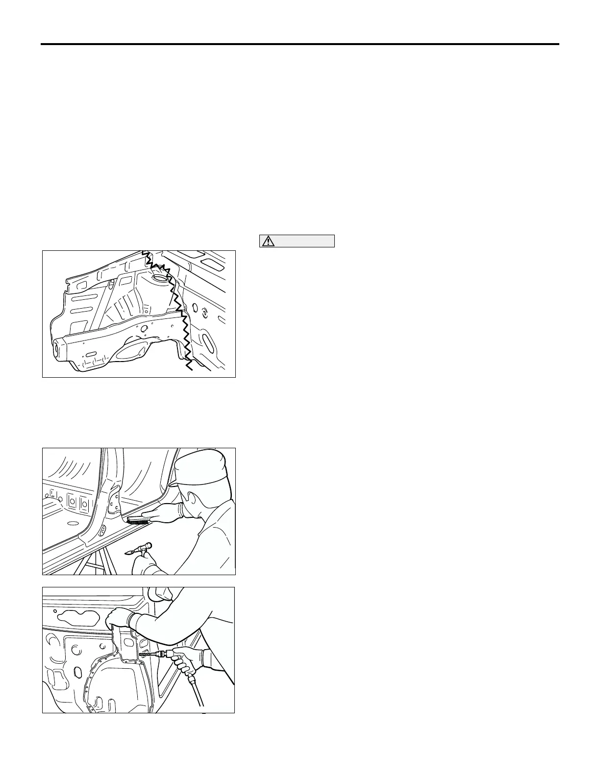
1. Rough cutting of panels
First make a rough cutting of a portion of the panel to be
replaced, and then remove that portion, thus making it
easier to break the spot welds.
2. Removal of the paint coat from spot-welded points
In order to clearly identify the spot-welded points, remove
the paint coat from areas where it is difficult to determine the
spot welds.
3. Cutting and separation of spot-welded points
In order to perform cutting and separation of spot-welded
points, use a spot weld cutter which is larger than the size of
the nugget to make a hole only in the panels to be replaced.
When cutting and separating spot-welded points in places
where the surrounding panel or other parts interfere with the
spot weld cutter, or if the operation is hampered by a lack of
space, bend back the flanges in order to make the work
easier.
If a spot-weld cutter cannot be used at all, cut and separate
the spot welds by using a chisel or similar tool.
AB200051
AB200052
AB200053

 Loading...