EasyManua.ls Logo

Mitsubishi QCPU (Q Mode) User Manual

Mitsubishi QCPU (Q Mode)
456 pages
To Next Page IconTo Next Page
To Previous Page IconTo Previous Page
Page #106 background imageLoading...
Page #106 background image
5 - 14 5 - 14
MELSEC-Q
5 ASSIGNMENT OF I/O NUMBERS
(c) Be sure to set the same module type for the mounted module and the I/O
assignment.
If the module type of the I/O assignment is different from that of the actually
mounted module, the module may not work normally.
For the intelligent function module, make sure that the numbers of I/O
points are the same.
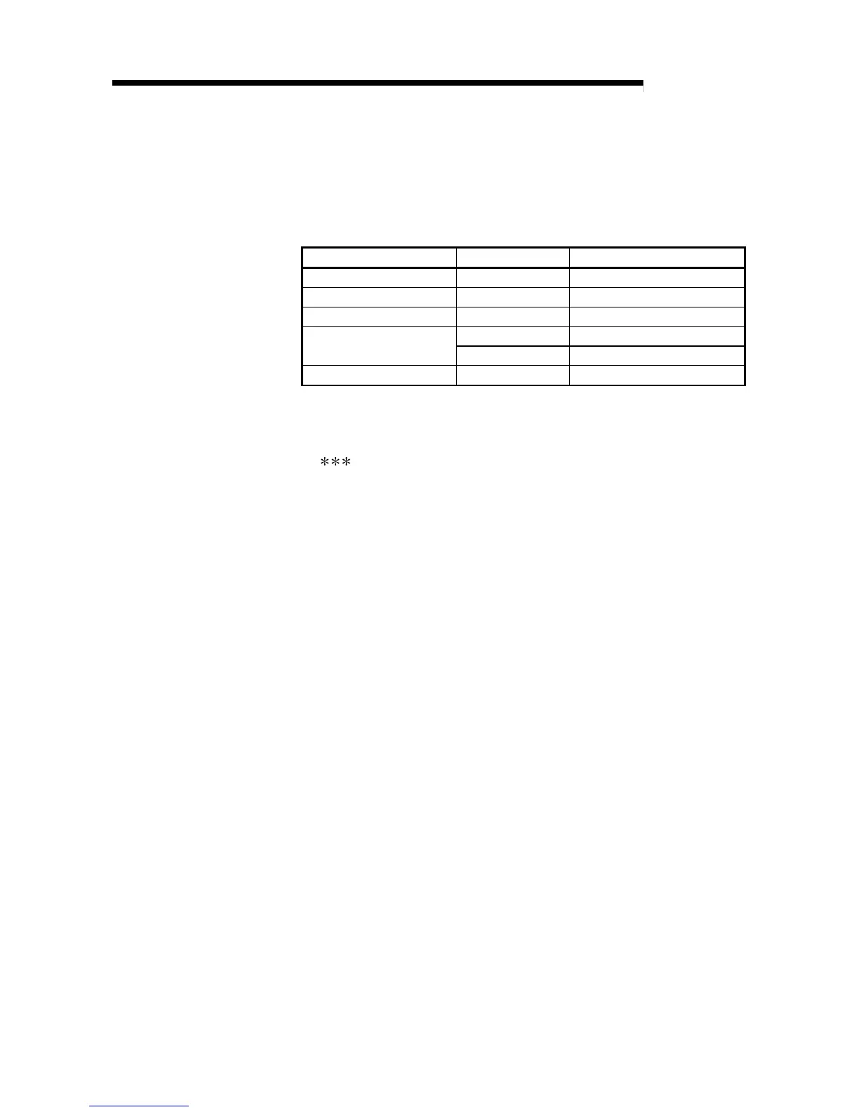
Actually installed module I/O assignment Result
Input module Output/Empty Empty
Output module Input/Empty Empty
Input module/output module Intelligent Error (SP. UNIT LAY ERR.)
Empty Empty
Intelligent function module
Input/output Error (SP. UNIT LAY ERR.)
Empty slot Intelligent No error occurs.
(d) Be sure to assign the I/O numbers so that the last I/O number is within the
range of FFF
H
or less. An error (SP. UNIT LAY ERR.) occurs when the last
I/O number exceeds FFF
H
. (System monitor of GX Developer shows
"
" as an I/O address.)

Table of Contents

Question and Answer IconNeed help?

Do you have a question about the Mitsubishi QCPU (Q Mode) and is the answer not in the manual?

Mitsubishi QCPU (Q Mode) Specifications

General IconGeneral
BrandMitsubishi
ModelQCPU (Q Mode)
CategoryController
LanguageEnglish

Summary

SAFETY INSTRUCTIONS

Design Precautions

Precautions related to the design of the PLC system and external circuits to ensure safety.

Installation Precautions

Wiring Precautions

Startup and Maintenance precautions

1 OVERVIEW

1.1 Features

Details the new features and improvements of the High Performance model QCPU.

1.2 Programs

Explains how programs are managed, constructed, and organized within the QCPU.

1.3 Convenient Programming Devices and Instructions

Describes devices and instructions that facilitate program creation and flexibility.

2 SYSTEM CONFIGURATION FOR SINGLE CPU SYSTEM

2.1 System Configuration

Outlines the equipment configuration, peripheral devices, and system setup for the QCPU system.

2.2 Precaution on System Configuration

Discusses hardware and software package compatibility and limitations for QCPU system configuration.

3 PERFORMANCE SPECIFICATION

4 SEQUENCE PROGRAM CONFIGURATION AND EXECUTION CONDITIONS

4.1 Sequence Program

Defines sequence programs, their types (main, sub-routine, interrupt), and basic structure.

4.2 Program Execute Type

Explains the different types of program execution (Initial, Scan, Low speed, Stand-by, Fixed scan) and how to set them.

4.3 Operation Processing

Describes the initial processing, I/O refresh, automatic refresh, and END processing steps.

4.4 RUN, STOP, PAUSE Operation Processing

Explains the operation processing for RUN, STOP, and PAUSE statuses of the High Performance QCPU.

4.6 Data Clear Processing

Explains the data clearing process, including device latch specification.

4.8 Numeric Values which Can Be Used in Sequence Programs

Covers the use of BIN, HEX, BCD, and Real number notations in sequence programs.

5 ASSIGNMENT OF I/O NUMBERS

5.1 Relationship Between the Number of Stages and Slots of the Extension Base Unit

Explains the relationship between extension base unit stages, slots, and module installation limits.

5.2 Installing Extension Base Units and Setting the Number of Stages

Details the types of extension base units and the procedure for setting stage numbers.

5.3 Base Unit Assignment (Base Mode)

Explains the "Auto" and "Detail" modes for assigning modules to base units.

5.5 Concept of I/O Number Assignment

Explains the concept of I/O number assignment for main and extension base units.

5.6 I/O Assignment by GX Developer

Describes the purpose and concept of I/O assignment using GX Developer.

5.7 Examples of I/O Number Assignment

Provides examples of I/O number assignment using GX Developer, including changing points for empty slots.

6 HIGH PERFORMANCE MODEL QCPU FILES

6.1 About the High Performance model QCPU's Memory

Details the QCPU's built-in memory types and memory card usage.

6.2 Program Memory

Explains the program memory, its data storage, and formatting procedures.

6.3 About the Standard ROM

Describes the standard ROM's purpose, data storage, and memory capacity.

6.4 About the Standard RAM

Explains the standard RAM's function, stored data, and formatting.

6.5 Memory Card

Details the types of memory cards supported, their capacities, and precautions.

6.6 Writing Data to the Standard ROM or the Flash Card

Explains how to write data to standard ROM or Flash card using GX Developer.

6.7 Executing Standard ROM/Memory Card Programs (Boot Run)

Explains how to execute programs stored in standard ROM or memory cards.

6.8 Program File Configuration

Details the structure of program files, including file header, execution program, and memory allocation.

7 FUNCTION

7.1 Function List

Provides a comprehensive list of functions and their corresponding reference sections.

7.2 Constant Scan

Explains the constant scan function for maintaining a constant scan time.

7.3 Latch Functions

Describes latch functions, their availability, and how to set the latch range.

7.4 Setting the Output (Y) Status when Changing from/to STOP Status to/from RUN Status

Explains how to set the output status when switching between RUN and STOP statuses.

7.5 Clock Function

Details the clock function for reading and using time data for system management.

7.6 Remote Operation

Covers remote operations like RUN/STOP, PAUSE, RESET, and latch clear.

7.7 Selecting the Response Speed of the Q Series Module (I/O Response Time)

Covers selecting response times for input, high-speed input, and interrupt modules.

7.8 Setting the Switches of the Intelligent Function Module

Guides on setting switches for intelligent function modules using GX Developer.

7.9 Monitoring Function

Describes the monitoring functions available through GX Developer.

7.10 Writing in Program during High Performance model QCPU RUN

Explains how to write programs or files while the QCPU is in RUN status.

7.11 Execution Time Measurement

Describes functions for displaying and measuring program execution times.

7.12 Sampling Trace Function

Explains the sampling trace function for checking device contents during debugging.

7.13 Debug Function with Multiple Users

Describes debugging capabilities for multiple users simultaneously.

7.14 Watch dog Timer (WDT)

Describes the watch dog timer function for detecting hardware and program errors.

7.15 Self-Diagnosis Function

Explains the self-diagnosis function for detecting and displaying errors.

7.17 System Protect

Covers system protection functions like password registration and remote passwords.

7.18 Monitoring High Performance model QCPU System Status from GX Developer (System Monitor)

Details how to monitor QCPU system status using GX Developer's System Monitor.

7.19 LED Display

Explains the status indicated by the LEDs on the High Performance model QCPU.

7.20 High Speed Interrupt Function

Covers the high-speed interrupt function for running programs with fixed-cycle interrupts.

7.21 Module Service Interval Time Reading

Explains how to monitor the service interval time of modules.

8 COMMUNICATION WITH INTELLIGENT FUNCTION MODULE/SPECIAL FUNCTION MODULE

8.1 Communication Between High Performance model QCPU and Intelligent Function Modules

Details methods for communication between QCPU and intelligent function modules.

8.1.1 Initial setting and automatic refresh setting using GX Configurator

Explains initial and automatic refresh settings for intelligent modules using GX Configurator.

8.1.2 Communication using device initial value

Covers using device initial values to set up intelligent function modules without a program.

8.1.3 Communication using FROM/TO instruction

Explains communication with intelligent function modules using FROM/TO instructions.

8.1.4 Communication using the intelligent function module device

Describes how to use intelligent function module devices for communication.

8.1.5 Communication using the instructions dedicated for intelligent function modules

Details instructions dedicated to intelligent function modules for programming.

8.2 Request from Intelligent Function Module to High Performance model QCPU

Explains how intelligent function modules can request interrupts to the QCPU.

8.3 Communication Between High Performance model QCPU and AnS Series Special Function Modules

Covers communication between QCPU and AnS series special function modules.

8.3.1 Communication using device initial value

Explains using device initial values for special function modules.

8.3.2 Communication using FROM/TO instruction

Details communication with special function modules using FROM/TO instructions.

8.3.4 Effects of quicker access to the special function module and countermeasures against them

Discusses effects of quick access to special function modules and countermeasures.

9 PARAMETER LIST

9.1 Parameter List

Provides a detailed list of PLC parameters, their numbers, descriptions, and reference sections.

10 DEVICES

10.1 Device List

Lists names and data ranges of devices usable in the High Performance model QCPU.

10.2 Internal User Devices

Covers internal user devices, their usable points, and memory capacity calculations.

10.2.1 Inputs (X)

Defines inputs (X) and explains how they are used in programs.

10.2.2 Outputs (Y)

Defines outputs (Y) and describes their usage and external output procedures.

10.2.3 Internal relays (M)

Explains the definition and usage of internal relays (M).

10.2.4 Latch relays (L)

Describes latch relays (L), their definition, and precautions.

10.2.5 Anunciators (F)

Explains annunciators (F) used for fault detection programs.

10.2.6 Edge relay (V)

Details edge relays (V) used for detecting leading edges.

10.2.7 Link relays (B)

Covers link relays (B) for MELSECNET/H network module communication.

10.2.8 Link special relays (SB)

Explains link special relays (SB) for communication status and error detection.

10.2.9 Step relays (S)

Defines step relays (S) as SFC program devices.

10.2.10 Timers (T)

Describes timers (T), their types, measurement units, and processing.

10.2.11 Counters (C)

Explains counters (C), their definition, count processing, and resetting.

10.2.12 Data registers (D)

Details data registers (D) for storing numeric data.

10.2.13 Link registers (W)

Covers link registers (W) for storing numeric data and network communication.

10.2.14 Link special registers (SW)

Explains link special registers (SW) for storing communication status and errors.

10.3 Internal System Devices

Describes internal system devices used for system operations.

10.3.1 Function devices (FX, FY, FD)

Details function devices (FX, FY, FD) used for data transfers in sub-routine programs.

10.3.2 Special relays (SM)

Explains the purpose and classification of special relays (SM).

10.3.3 Special registers (SD)

Describes the purpose and classification of special registers (SD).

10.4 Link Direct Devices (J \)

Covers link direct devices used for accessing link devices in network modules.

10.5 Intelligent Function Module Devices (U \G )

Explains how QCPU directly accesses buffer memories of intelligent function modules.

10.6 Index Registers (Z)

Details index registers (Z) used for indirect setting and index modification.

10.6.1 Switching between scan execution type programs and low speed execution type programs

Explains index register processing when switching between scan and low speed execution types.

10.7 File Registers (R)

Describes file registers (R) as expansion devices for data registers.

10.7.1 File register capacity

Details the capacity of file registers in standard RAM, SRAM, and Flash cards.

10.7.3 Registering the file registers

Guides on registering file registers with the QCPU.

10.8 Nesting (N)

Describes nesting devices for MC or MCR master control instructions.

10.9 Pointers (P)

Explains pointer devices used in jump and sub-routine call instructions.

10.9.1 Local pointers

Details local pointers for independent use in programs.

10.9.2 Common pointers

Explains common pointers for calling sub-routines across all programs.

10.10 Interrupt Pointers (I)

Describes interrupt pointers used as labels for interrupt programs.

10.11 Other Devices

Covers other devices like SFC block and network designation devices.

10.12 Constants

Explains decimal and hexadecimal constants used in sequence programs.

10.13 Convenient Uses for Devices

Explains convenient uses for devices, including global and local devices.

10.13.1 Global devices and local devices

Differentiates between global and local devices and their usage.

10.13.2 Device initial values

Explains using device initial values to set data without a program.

11 HIGH PERFORMANCE MODEL QCPU PROCESSING TIME

11.1 Reading High Performance model QCPU's Scan Time

Explains how to calculate scan time by summing I/O refresh, instruction execution, and END processing times.

11.2 Factors Responsible for Extended Scan Time

Lists functions that increase scan time, such as network refresh and sampling trace.

12 PROCEDURE FOR WRITING PROGRAMS TO HIGH PERFORMANCE MODEL QCPU

12.1 Writing Procedure for 1 Program

Details the steps and considerations for writing a single program to the QCPU.

12.2 Procedure for Multiple Programs

Explains the procedure for writing and executing multiple programs.

13 OUTLINE OF MULTIPLE PLC SYSTEMS

13.1 Features

Highlights the advantages of multiple PLC systems, such as multi-control and load dispersion.

13.2 Outline of Multiple PLC Systems

Explains what a multiple PLC system is and its configuration.

13.3 Differences with Single CPU Systems

Compares multiple PLC systems with single CPU systems, noting differences in function versions, mounting, parameters, and I/O numbers.

14 SYSTEM CONFIGURATION OF MULTIPLE PLC SYSTEM

14.1 System Configuration

Details the equipment configuration for multiple PLC systems.

14.2 Precautions For Multiple PLC System Configuration

Covers precautions for configuring multiple PLC systems, including function versions and mounting positions.

14.2.1 Function versions of High Performance model QCPU, motion CPUs and PC CPU module that can be used, and their mounting positions

Explains allowable function versions and mounting positions for QCPU, motion, and PC CPU modules in multiple PLC systems.

14.2.2 Precautions when using Q Series I/O modules and intelligent function modules

Lists precautions when using Q Series I/O and intelligent function modules in multiple PLC systems.

14.2.3 Limitations when mounting AnS Series corresponding I/O modules and special function modules

Details limitations when mounting AnS Series I/O and special function modules.

14.2.5 Compatible GX Developers and GX Configurators

Lists compatible GX Developers and GX Configurators for multiple PLC systems.

14.2.6 Parameters that enable the use of multiple PLC system

Covers parameters required for enabling multiple PLC system operation.

14.2.7 Resetting the multiple PLC system

Explains the procedure and precautions for resetting a multiple PLC system.

14.2.8 Processing when High Performance model QCPU stop errors occur

Details how the system handles stop errors in PLC No.1 and other PLCs.

14.2.9 Reducing the time required for multiple PLC system processing

Provides methods for reducing processing time in multiple PLC systems.

15 ALLOCATING MULTIPLE PLC SYSTEM I/O NUMBERS

15.1 Concept behind Allocating I/O Numbers

Discusses the concept of I/O number allocation for interactive transmission.

15.1.1 I/O modules and intelligent function module I/O numbers

Covers I/O numbers for modules mounted on base units and the "00H" position.

15.2 Purpose of PC Parameter I/O Allocations with GX Developer

Explains the purpose of PC parameter I/O allocations using GX Developer.

16 COMMUNICATION BETWEEN CPU MODULES IN MULTIPLE PLC SYSTEM

16.1 Automatic Refresh of CPU Shared Memory

Explains automatic refresh of CPU shared memory for data transfer between CPUs.

16.2 Communication with Multiple PLC Instructions and Intelligent Function Module Devices (U \G )

Details communication using S. TO, FROM instructions and intelligent function module devices.

16.3 Interactive Communications between The High Performance model QCPU and Motion CPU

Covers control commands and device data read/write between QCPU and Motion CPU.

16.4 CPU Shared Memory

Describes the structure and usage of CPU shared memory.

17 COMMUNICATIONS BETWEEN THE MULTIPLE PLC SYSTEM'S I/O MODULES AND INTELLIGENT FUNCTION MODULES

17.1 Range of Control PLC Communications

Describes the communication range between control PLCs and control modules.

17.2 Range of Non-control PLC Communications

Covers communication possibilities for non-control PLCs.

17.3 Accessing input (X) from input modules and intelligent function modules

Explains loading input data from modules controlled by other PLCs.

17.4 Loading output (Y)

Details loading output data from modules controlled by other PLCs.

17.5 Accessing MELSECNET/H modules

Covers accessing MELSECNET/H modules, noting restrictions.

18 PROCESSING TIME FOR MULTIPLE PLC SYSTEM HIGH PERFORMANCE MODEL QCPUs

18.1 Concept behind CPU Scanning Time

Explains the concept of scanning time in multiple PLC systems.

18.2 Factor to Prolong the Scan Time

Lists functions that prolong scan time, such as network refresh and sampling trace.

19 STARTING UP THE MULTIPLE PLC SYSTEM

19.1 Flow-chart for Starting Up the Multiple PLC System

Outlines the step-by-step process for starting up a multiple PLC system.

19.2 Setting Up the Multiple PLC System Parameters (Multiple PLC Settings, Control PLC Settings)

Details procedures for setting up multiple PLC system parameters using GX Developer.

19.2.1 System configuration

Provides an example procedure for setting up multiple PLC system parameters.

19.2.2 Creating new systems

Guides on creating new multiple PLC system configurations.

19.2.3 Using existing preset multiple PLC settings and I/O allocations

Explains how to transfer and use existing multiple PLC settings and I/O allocations.

APPENDICES

APPENDIX 1 Special Relay List

Lists and explains special relays (SM) used in the PLC for system control.

APPENDIX 2 Special Register

Lists and explains special registers (SD) used for storing QCPU status data.

APPENDIX 3 List of Interrupt Pointer Nos. and Interrupt Factors

Provides a list of interrupt pointers and their associated interrupt factors.

Related product manuals