4 - 15
4 Configuration and Wiring
AC Servomotors/Servo Drives 1S-series with Built-in EtherCAT® Communications User’s Manual (I586)
4-1 Installation Conditions
4
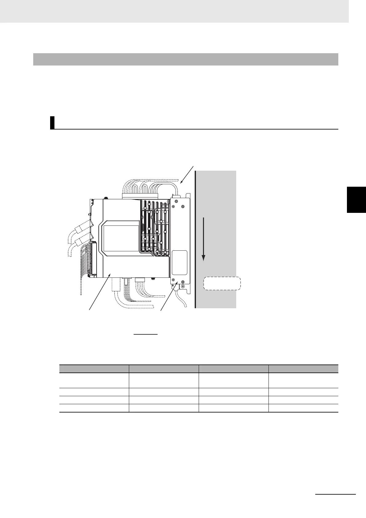
4-1-5 Footprint-type Noise Filter Installation Conditions
Satisfy the space conditions around Servo Drives that are described in 4-1-1 Servo Drive Installation
Conditions on page 4-2.
Use the attached exclusive screws when you mount the Servo Drive to the Noise Filter. The tightening
torque for the exclusive screws is 1.2 N·m±10%.
Install the Noise Filter on the vertical metal surface.
Turn the LINE side of Noise Filter in the gravity direction (downward) as shown in the following figure.
4-1-5 Footprint-type Noise Filter Installation Conditions
Mounting Direction
Noise filter model Wire size Length Strip length
R88A-FI1S103/-FI1S105/
-FI1S202/-FI1S203
AWG 16 Approx. 300 mm 8.5±0.5 mm
R88A-FI1S109/-FI1S208 AWG 14 Approx. 300 mm 8.5±0.5 mm
R88A-FI1S116/-FI1S216 AWG 10 Approx. 300 mm 13.7±0.5 mm
R88A-FI1S309 AWG 12 Approx. 300 mm 13.7±0.5 mm
Lead wire
*2
Noise filter
Side view
Servo Drive
*1. Power supply side
*2. The specifications of the lead wires are shown below.
Metal plate
Gravity
direction
LINE
*1

 Loading...
