5 - 3
5 EtherCAT Communications
AC Servomotors/Servo Drives 1S-series with Built-in EtherCAT® Communications User’s Manual (I586)
5-1 Display Area and Settings
5
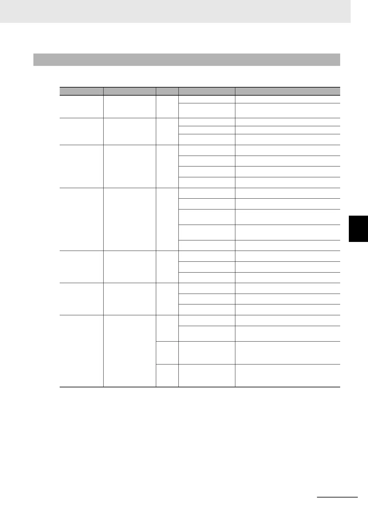
5-1-2 Status Indicators
The following table shows the status indicators and their meaning.
5-1-2 Status Indicators
Name Function Color Status Description
PWR Displays the sta-
tus of control
power supply.
Green OFF Control power supply OFF
ON Control power supply ON
ERR Displays Unit error
status.
Red OFF No error
ON Error detected
Flashing A warning occurred
ECAT-RUN Displays the sta-
tus of ESM.
Green OFF Init state or power OFF state
Blinking Pre-Operational state
Single flash Safe-Operational state
ON Operational state
ECAT-ERR Displays Ether-
CAT communica-
tions error status.
Red OFF No error
Blinking Communications setting error
Single flash Synchronization error or communica-
tions data error
Double flash Application WDT timeout (Sync Manager
WDT Error)
ON A fatal error such as WDT timeout
L/A IN Displays link sta-
tus in EtherCAT
physical layer.
Green OFF Link not established in physical layer
ON Link established in physical layer
Flickering In operation after link was established
L/A OUT Displays link sta-
tus in EtherCAT
physical layer.
Green OFF Link not established in physical layer
ON Link established in physical layer
Flickering In operation after link was established
FS Displays FSoE
communications
status.
Green ON FSoE slave connection established
Flashing FSoE slave connection establishment in
progress
Red Flashing Safety Parameter Error, Safety
Communications Timeout, or other
errors
--- OFF STO via FSoE is disabled, the power is
not supplied, or a fatal error including
Self-diagnosis Error

 Loading...
