120
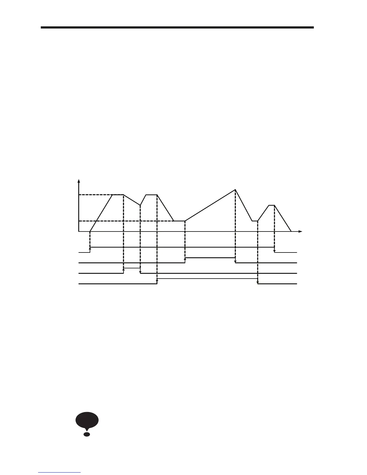
Up/Down Command 2 by time and return to original frequency
reference when S6, S7 = OFF
n056 = 36 Up/Down command 2 on S6 / S7
n003 = 1 Run command source is digital input
n004 = 1 Main frequency reference input is n024
n045 = 0 Frequency reference bias is changed by time
n046 = 1 Use Acceleration / Deceleration time 4
n047 = 1 Bias value is held if S6, S7 are both ON or OFF
n100 = 1 Bias value is saved to EEPROM
Using the Multi-function Analog Inputs (n077, n078, n079)
The input analog signal (0 to 10 V or 4 to 20 mA) for the CN2 terminal
of the JVOP-140 Digital Operator can be used as an auxiliary function
for the master frequency reference input to the control circuit terminals
(FR or RP). Refer to the block diagram on page 167 for details on the
input signal.
When using the signal for the CN2 terminal of the JVOP-140
Digital Operator as a multi-function analog input, never use it
for the target value or the feedback value of PID control.
RUN command
UP2 Command
DOWN2 Command
Multi-step speed
command
FOUT (Hz)
n 024 ( 35 H z)
10Hz
35Hz
n 025 ( 10 H z) n 024 ( 35 H z)
Accel 1
Decel 4
Decel 1
Accel 4
TIME
Accel 1
Decel 1
Accel 1
Decel 1
NOTE
 Loading...


