142
Communications Specifications
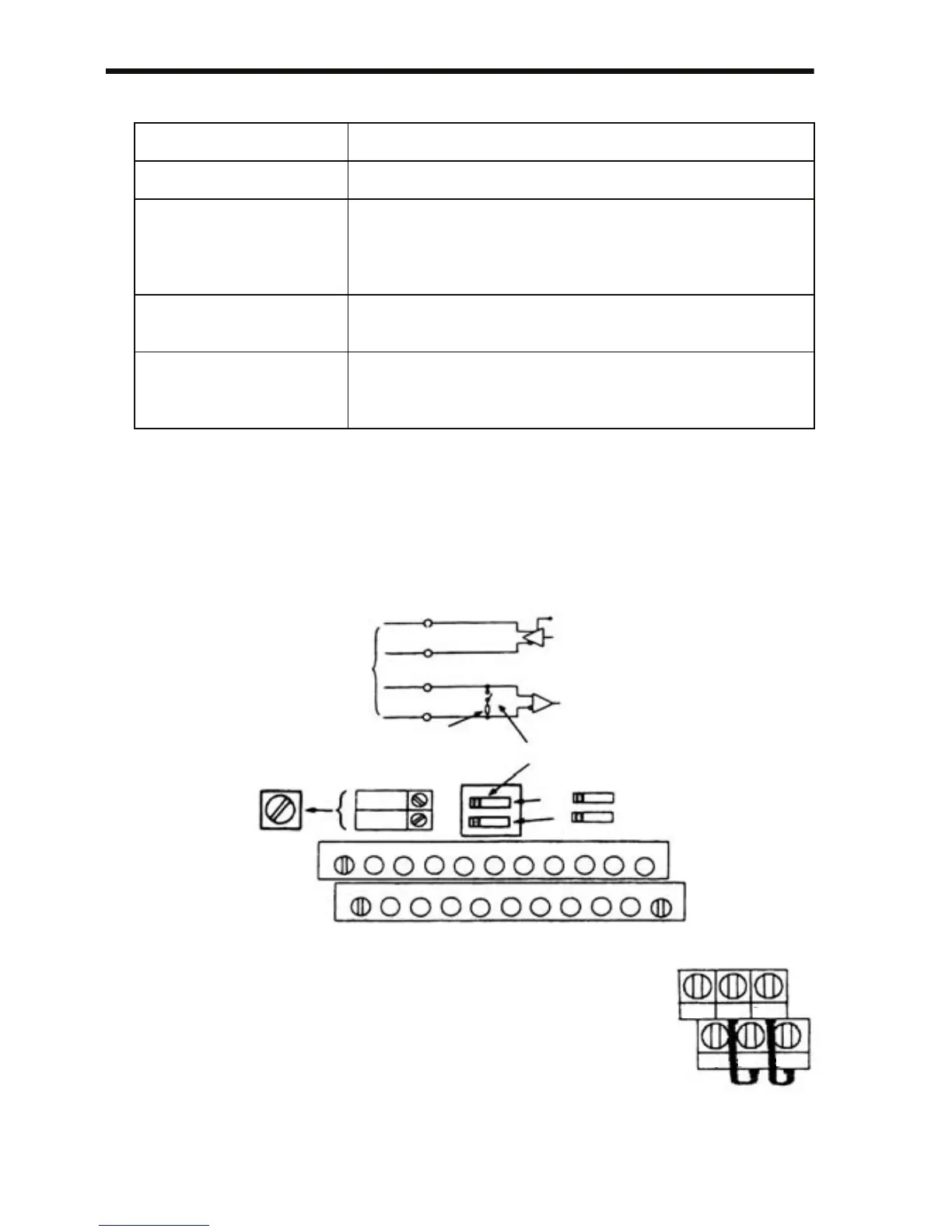
Communications Connection Terminal
Use the following S+, S-, R+ and R- terminals for MEMOBUS commu-
nications. Change the termination resistor as shown below.
At RS-422, RS-485 communications: Turn ON SW2 ON/OFF switch of
only the Inverter at the termina-
tion viewed from the PLC.
Note: 1. Separate the wiring for communication from the
main circuit wiring or other power lines.
2. Use shielded cables for communication wiring;
connect the shielded sheath to the ground terminal
and terminate the other end to prevent it from
being connected (to prevent noise malfunction).
3. When communication is performed through RS-
485, connect S+ and R+, S- and R- terminals outside the Inverter as
shown at the right.
Interface RS-422, RS-485
Synchronization Asynchronous (Start-stop synchronization)
Communication
Parameters
Baud rate: Selected from 2400/4800/9600/19200 bps
Data length: 8 bits fixed
Parity: Selected from even/odd/none
Stop bits: 1 bit fixed
Communication
Protocol
MEMOBUS (MODBUS) (RTU mode only)
Max. Number of
Inverters That Can Be
Connected
31 (When using RS-485)
RS-422A
or RS-485
S+
SW2
SW1
I
SW2
PNP
NPN
OFF
ON
V
S-
R+
R+ R- FS FR FCS5 S6 S7 P1 P2
S1 S2 S3
S4 SC PC
S+ S- AM AC
RP
R-
SW2 ON/OFF Switch
Terminal Resistor (1/2 W, 120 Ω)
S-
R-
PC
P2
R+
S+
 Loading...


