36
Wiring the Control Circuits
Only basic insulation is provided for the control circuit terminals.
Additional insulation may be necessary in the end product.
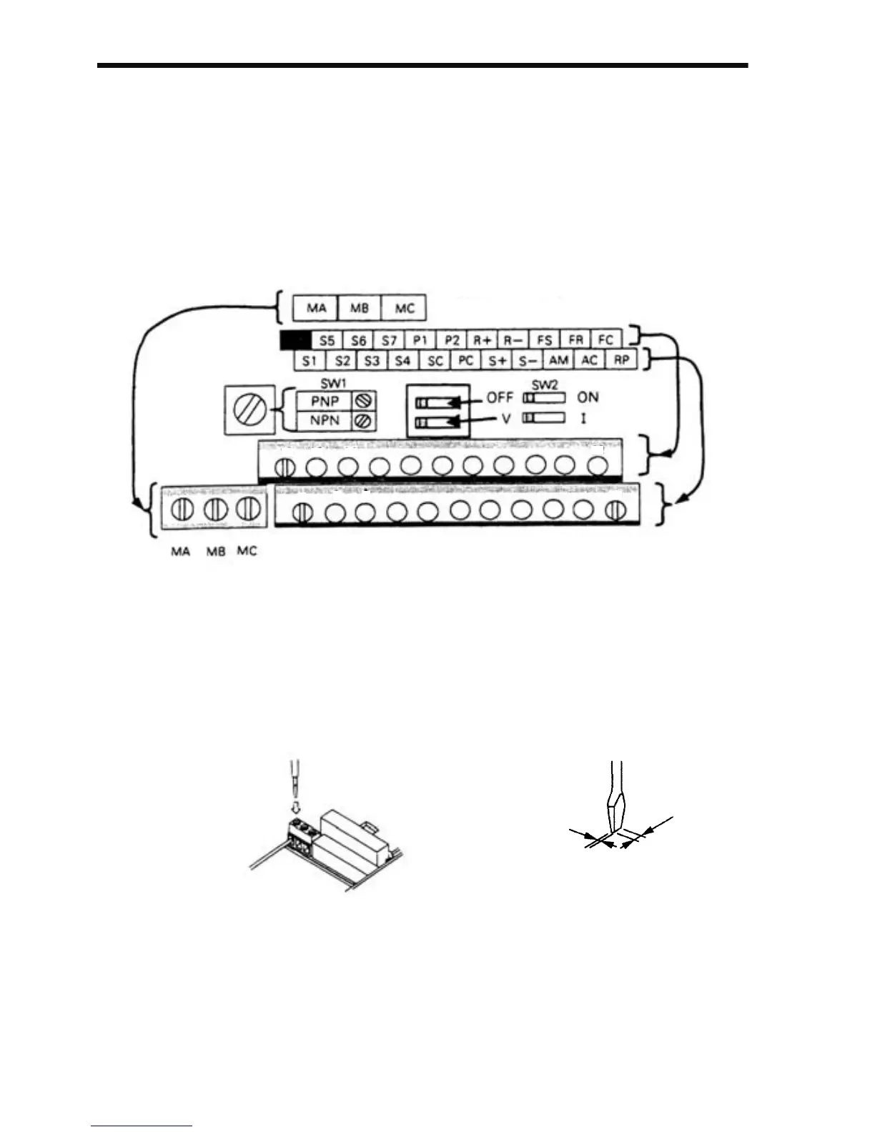
• Control Circuit Terminals
Pass the cable through the wiring hole to connect it. Always mount
the cover in its original position.
SW1 can be changed according to sequence input signal (S1 to S7)
polarity.
0 V common: NPN side (factory setting)
+24 V common: PNP side
Refer to pages 226 and 227 for SW1.
Refer to pages 126 and 142 for SW2.
Insert the wire into the lower part of the terminal block and connect
it tightly with a screwdriver.
Contact Output
0.4 mm max
(0.016 in.)
2.5 mm max
(0.098 in.)
Screwdriver Blade WidthWiring the Control Circuit Terminals
 Loading...


