Installation Section 1-5
14
Note 1. Use the same tightening torque for the left and right screws. The laser
beam may be distorted if the tightening torque is not the same.
2. If the screws are tightened at a stronger torque than specified, the
screw holes may be damaged. Use the specified torque. Be sure to
use the M2 screws provided with the Side-view Attachment when
mounting.
3. When using the Side-view Attachment, adjust the optical axis after
mounting the Attachment. Be sure to set the reference incident level
after adjusting the optical axis.
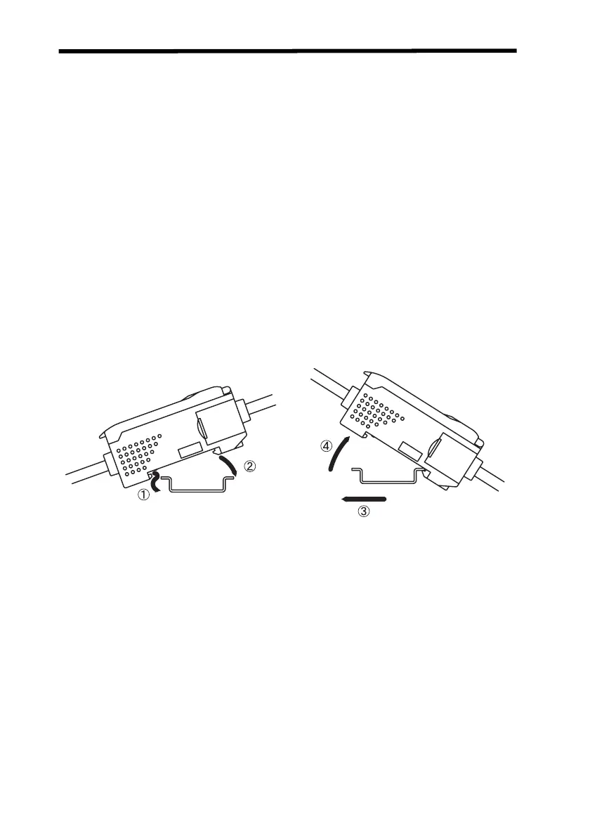
1-5-3 Amplifier Unit
Note: Always mount the front of the Unit first. Mounting strength may decrease
if mounting is performed in the reverse order.
DIN Track
DIN Track
Mounting
1. Mount the front of the Unit to the
DIN Track.
2. Press the rear of the Unit onto
the DIN Track.
Removing
1. Press the Unit toward the
front.
2. Lift the front of the Unit.
Z157-E1-01C.book Page 14 Thursday, August 31, 2006 5:13 PM

 Loading...