Part Names and Functions Section 2-1
20
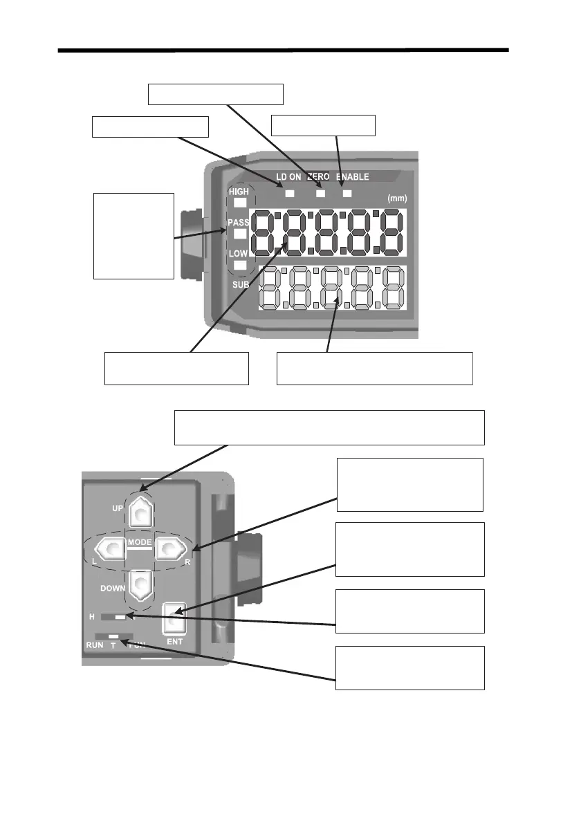
2-1 Part Names and Functions
Note 1. The current/voltage switch for the linear output is on the bottom of the
Amplifier Unit.
2. The information displayed on the main display and sub-display is
reversed if Reverse Mode is enabled.
Zero reset indicator (green)
Laser ON indicator (green)
Enable indicator (green)
Sub-display
Threshold value, incident level, resolution, etc.
Main display
See note 2.
Measured value, function, etc.
Judgement
indicators
HIGH (orange)
PASS (green)
LO W (yellow)
See note 2.
Change Keys
Changing function, threshold values, set values, etc.
Selection Keys
RUN mode displays, function
switching, numeric digit selection,
etc.
ENT Key
Zero reset, teaching, function/
numeric value confirmation
Threshold Switch
Selecting H or L
Mode Switch
Selecting RUN, T, or FUN
Z157-E1-01C.book Page 20 Thursday, August 31, 2006 5:13 PM

 Loading...