5.47
ENGINE
5
Connecting Rod Inspection
1. Secure connecting rod lightly in a soft jawed vise.
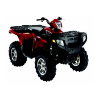
2. Note location of the piston circlip gap (A) at top.
3. Remove piston circlip.
4. Push piston pin out of piston. If necessary, heat crown of
piston slightly with a propane torch or heat gun.
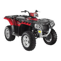
5. Measure piston pin O.D. in two directions and 3 locations
on the length.
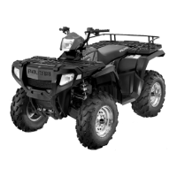
6. Inspect small end and big end of connecting rod (and
matching rod cap) for damage, galling of surface or pitting.
7. Measure small end I.D. in two directions as shown. Record
measurements. Difference between measurements is
concentricity. Compare to specifications.
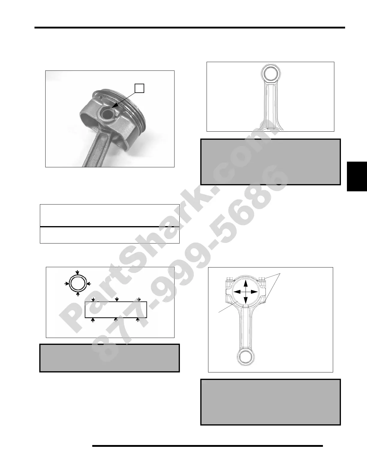
8. Install matching rod cap on connecting rod (without
bearings) and install bolts.
9. Tighten bolts snug, then torque to 24 lb-ft (33 Nm).
10. Using a dial bore gauge, measure big end I.D. in two
directions shown. Record measurements. Difference
between measurements is concentricity. Compare to
specifications.
11. Select appropriate bearing insert (color) from table
(page 5.48).
NOTICE
Do not apply heat to piston rings or a loss of radial
tension could result.
Piston Pin O.D. :
0.7873" ± .0001" (19.9975 ± .0025 mm)
A
Connecting Rod (Small End) Diameter:
0.7886 + 0.0 / - .015" (20.03 + 0.0 / - .015 mm)
Connecting Rod (Small End) Concentricity:
< 0.00027" (0.007 mm) Out Of Round
Connecting Rod (Big End) Diameter:
1.8892 - 1.8902" (47.987 - 48.011 mm)
Connecting Rod (Big End) Concentricity:
< 0.00047" (0.012 mm)
Install New
1. Tighten snug
2. Torque 24 lb-ft. (33 Nm)
Remove
bearings
PartShark.com
877-999-5686
 Loading...