7.8
CLUTCHING (PVT)
4. Install the cover and torque the inner PVT cover screws to
specification.
5. Wipe away any excess silicone sealant.
6. Clean the splines inside the driven clutch and on the
transmission input shaft.
7. Apply a light film of grease to the splines on the shaft.
8. Install the driven clutch, cup washer, lock washer, and
retaining bolt. Torque retaining bolt to specification.
9. Clean end of taper on crankshaft and the taper bore inside
drive clutch using a tapered reamer.
10. Install the drive clutch, bushing, washer, lock washer, and
the left-hand threaded retaining bolt. Torque retaining bolt
to specification.
11. Install drive belt noting direction of rotation if the belt is
being reused (see “DRIVE BELT - Belt Installation”, steps
1-3).
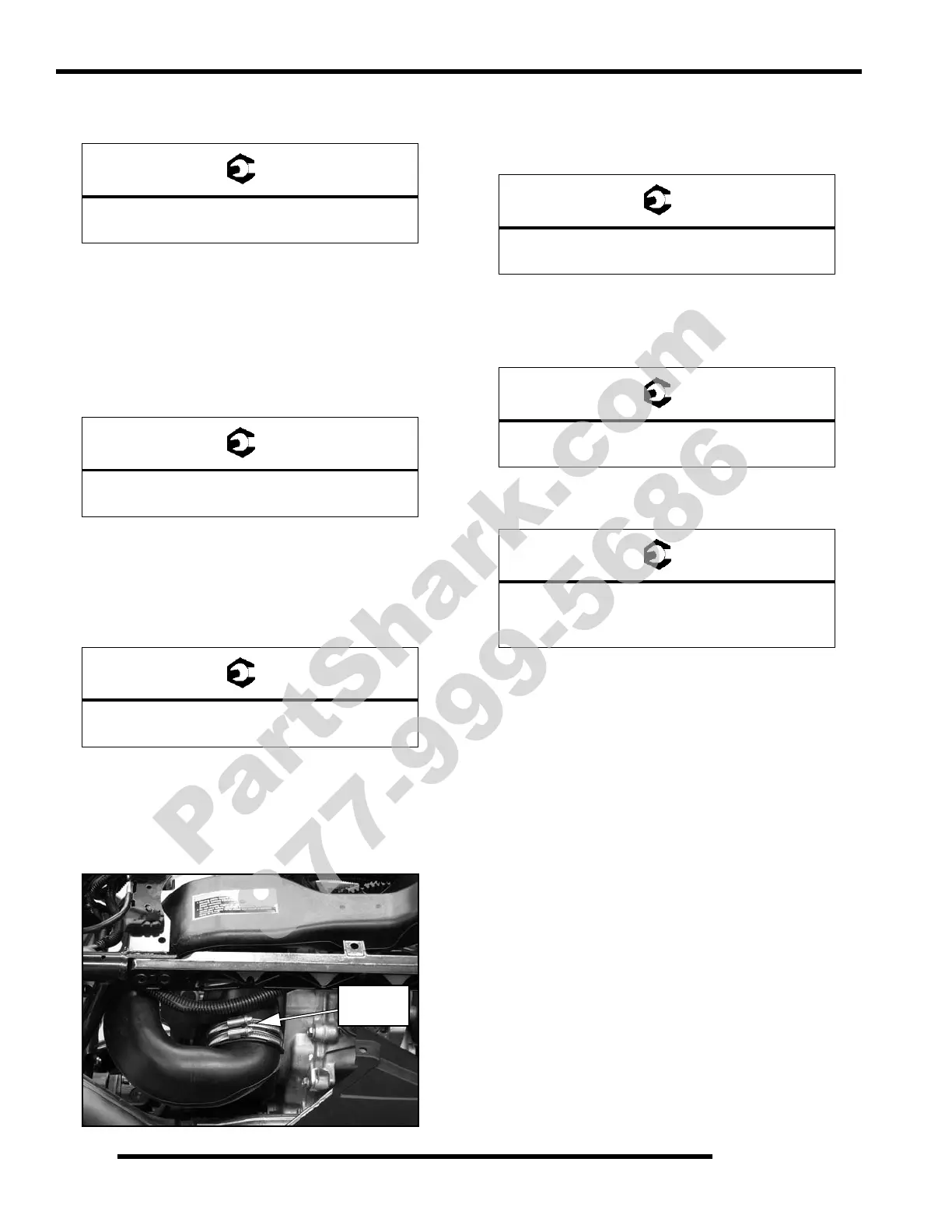
12. Install the PVT outlet duct. Align the duct with the inner
PVT cover properly before tightening the hose clamps.
13. Replace the outer PVT cover seal.
14. Reinstall outer PVT cover and secure with screws. Torque
screws to specification.
15. Reinstall the rear cab, tail light bulbs, and fasteners.
16. Reinstall the lower left-hand frame support and torque bolts
to specification.
17. Install the left rear wheel and torque wheel nuts to
specification.
18. Lower the ATV, start the engine, and test the operation of
the PVT system.
= T
Inner PVT Cover Screws:
6-8 ft. lbs. (8-11 Nm)
= T
Driven Clutch Retaining Bolt:
13 ft. lbs. (18 Nm)
= T
Drive Clutch Retaining Bolt:
47 ft. lbs. (64 Nm)
Tighten
Clamps
= T
Outer PVT Cover Screws:
45-50 in. lbs. (5-5.6 Nm)
= T
Lower Left-Hand Frame Support Bolts:
36 ft. lbs. (49 Nm)
= T
Wheel Nuts:
Steel: 45 ft. lbs. (61 Nm)
Aluminum: 75 ft. lbs. (102 Nm)
PartShark.com
877-999-5686
 Loading...