ELECTRICAL
10.16
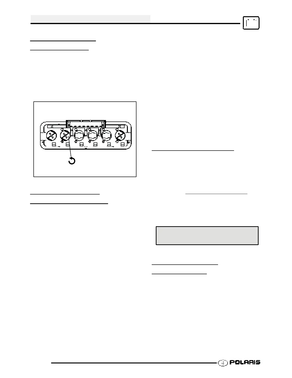
INDICATOR LAMP
REPLACEMENT
1. Disconnect indicator light harness from the panel
by lifting the retaining latch.
2. To remove defective lamp: Use a small
screwdriver and turn lamp holder a quarter turn,
pull the bulb assembly out with a needle nose
pliers or equivalent. Replace with a new bulb
assembly.
Rear view of indicator lamp panel
1/4 Turn To Remove
STARTER SYSTEM
TROUBLESHOOTING
Starter Motor Does Not Turn
GBattery discharged. Low specific
gravity
GLoose or faulty battery cables or
corroded connections (see Voltage
Drop Tests)
GRelated wiring loose, disconnected, or
corroded
GPoor ground connections at battery
cable, starter motor or starter
solenoid (see Voltage Drop Tests)
GFaulty key switch
GFaulty kill switch
GFaulty starter solenoid or starter motor.
GEngine problem - seized or binding (Can
engine be rotated easily with recoil
starter?)
Starter Motor Turns Over Slowly
GBattery discharged - low specific
gravity
GExcessive circuit resistance - poor
connections (see Voltage Drop Test
below)
GEngine problem - seized or binding
(Can engine be rotated easily?)
GFaulty or worn brushes in starter
motor
GAutomatic compression release
inoperative
Starter Motor Turns - Engine Does Not Rotate
GFaulty starter drive
GFaulty starter drive gears or starter
motor gear
GFaulty flywheel gear or loose flywheel
VOLTAGE DROP TEST
The Voltage Drop Test is used to test for bad
connections. When performing the test, you are
testing the amount of voltage drop through the
connection. A poor or corroded connection will
appear as a high voltage reading. Voltage shown on
the meter when testing connections should not
exceed .1 VDC per connection or component
.
To perform the test, place the meter on DC volts and
place the meter leads across the connection to be
tested. Refer to the chart on 10.27 to perform voltage
drop tests on the starter system.
Voltage should not exceed
.1 DC volts per connection
STARTER MOTOR
DISASSEMBL
Y
NOTE: Use only electrical contact cleaner to clean
starter motor parts. Some solvents may leave a
residue or damage internal parts and insulation.
1. Note the alignment marks on both ends of the
starter motor casing. These marks must align
during reassembly.
 Loading...