14 Rockwell Automation Publication 750-AT006D-EN-P - January 2022
Chapter 1 Background
because they generate more phase lag than notch filters. As a result, only apply low pass filters if you run out of notch filters, and only
reserve them for resonances with the highest resonant frequencies.
Load Side Resonances
Even when all motor side resonances are suppressed and the motor shaft is tightly controlled using closed loop feedback, the load end
effector can still oscillate at a few Hertz through a compliant mechanical connection or linkage to the motor. These oscillations are load side
resonances that are unobservable in the feedback signal and are not measurable by the feedback device on the motor. Load side
resonances result in end effector vibration that is common in robots, cranes, cantilevered loads, anti-sway, liquid sloshing, laser cutting, and
material handling applications.
Load side resonance suppression requires one of the following techniques, or a combination of them:
• Determine the load oscillation frequency with a stopwatch and apply a reference notch filter at that frequency. Then select a smooth
reference move profile. This technique is recommended, and is the simplest to implement.
• Select a move type in 10:931 [Ref Move Type] that generates a reference profile that will not excite the load side resonance. Choices
for move type are: LinScurve, SineSquared, Poly5, and Cubic.
• Determine the load oscillation frequency with a stopwatch and generate a smooth reference CAM profile that does not contain any
load oscillation frequency content.
• Place a feedback device on the load and set the drive to load side feedback mode
See Position Loop
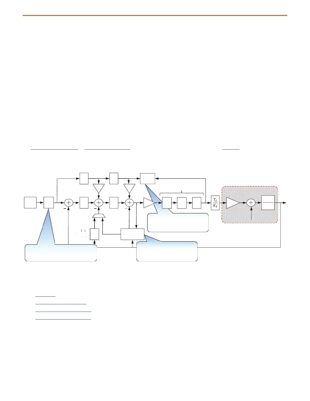
on page 20 or Velocity Loop on page 21 for more information on reference notch filters. Figure 10 shows which features
are used to control various resonances.
Figure 10 - Controlling Resonance
Performance
The following sections describe the metrics that are used to adjust performance during tuning:
• Bandwidth
• Damping Factor on page 16
• System Bandwidth on page 16
• System C/U Select on page 18
Adaptive Tuning compensates
• MF Resonances
• HF Resonances
2
1
sJ
T
PI
s
PI
s
Fs
K
T
P
REG
V
REG
Velocity
Feedback
Filter
Position
Feedback
Velocity
Estimate
Feed
Forwards
Kvff Kaff
Position
Command
LP
LL
N
Torque Loop Filters
Load Torque
Load
Observer
K
J
Torque
Estimate
Adaptive
Tuning
RN
System Under Control
P
REF
Load Observer compensates
• Inertia
• LF Resonances
e
Reference Notch Filters compensate
• Load Resonances
 Loading...


