16 Rockwell Automation Publication 750-AT006D-EN-P - January 2022
Chapter 1 Background
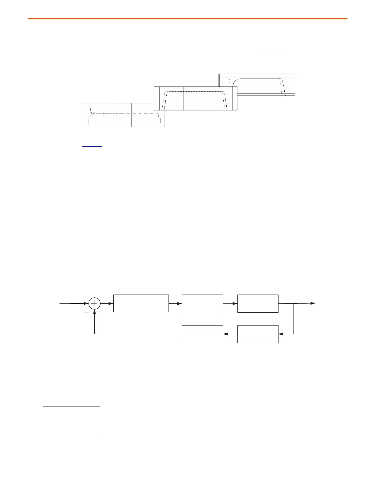
Damping Factor
The damping factor is commonly referred to as zeta (Z). It affects the rise time for a given bandwidth. Figure 13 shows how the damping
factor affects actual response (solid) compared to its reference move profile (dashed). Here, feed forward gains are disabled.
Figure 13 - How Damping Affects Transient Response
The examples shown in Figure 13
are discussed:
• A damping factor of Z < 1 produces high responsiveness, which is characterized by a faster rise time with overshoot.
• A damping factor of Z = 1 produces medium responsiveness, which is characterized by the fastest possible rise time without
overshoot. This value is the default and recommended setting.
• A damping factor of Z > 1 produces low responsiveness, which is characterized by a slower response without overshoot, similar to
decreasing the bandwidth.
10:907 [System Damping] adjusts the position, velocity, and torque loop spacing of the calculated control loop gains and load observer gains.
It also adjusts the integrator spacing of calculated gain parameters to generate the required responsiveness.
A lower damping factor decreases the spacing between the position, velocity, and torque loop bandwidths. It also increases integrator gains.
This value generates under-damped responses in the position and velocity response. A higher damping factor generates over-damped
responses.
System Bandwidth
System bandwidth is calculated from an internal quantity that is called the drive model time constant (DMTC). The DMTC is the sum of all
delays around the torque loop for a given drive and motor combination.
Figure 14 - Delays Associated with DMTC
The following parameters are used to calculate the DMTC.
• 10:445 [VCL CReg BW] – This parameter is the current regulator bandwidth
• 10:407 [Motor Poles] – This parameter is the number of motor poles (p). It is calculated as follows
p = round (120 x [Motor NP Hertz] / [Motor NP RPM])
• Primary Encoder Resolution – This parameter is the total resolution in edge counts per revolution (EPR) specified by parameters on
the primary feedback option card.
Low-Resolution Example:
Resolution = 1024 pulses per revolution * 4 quadrature edge counts per pulse = 4096 EPR (12-bit). The low-
resolution PPR comes directly from a parameter on the option card. When both A and B channels are selected for an incremental
encoder, the edge count multiplier is 4. This value is the typical and default setting. When only channel A is selected, then the edge
count multiplier is 2.
High-Resolution Example:
Resolution = 1024 pulses per revolution * 1024 edge counts per pulse = 1,048,576 EPR (20-bit). For high-
resolution devices, the overall resolution choices are 20-bit default or an optional 24-bit when the corresponding configuration bit is
selected.
Under Damped
High: Z < 1
Over Damped
Low: Z > 1
Critically Damped
Medium: Z = 1
PI Regulator
Computational Delay
Command
Current Loop
Time Constant
Motor Electrical
Time Constant
Feedback
Sample Delay
Feedback Filter
Time Constant
Actual
 Loading...


