Rockwell Automation Publication 750-AT006D-EN-P - January 2022 17
Chapter 1 Background
Typical values for current regulator bandwidth are given for various drive carrier frequencies in Table 1.
The bandwidth that is associated with the DMTC is the torque loop bandwidth.
10:906 [System BW] – System bandwidth is calculated using the torque loop bandwidth and the following parameters.
10:901 [Load Ratio]
10:902 [Load Coupling]
10:907 [System Damping]
10:1000 [Pri Vel Fb Sel] – Enter the 2-digit port location followed by the 4-digit parameter number of the primary feedback device.
System bandwidth is used in the calculated control loop parameters. It is also used as a tuning knob. See Single Knob Tuning
on page 61 for
more information.
Encoderless Mode:
In this mode, 10:906 [System BW] is set to a conservative value of 2 Hz. See the definition of Encoderless Mode in the
Manual Tuning chapter introduction on page 76.
10:1010 [Alt Fb GnScale] – Similar to how system bandwidth adjusts multiple calculated control loop parameters, this parameter internally
scales control loop gains and filter bandwidths during alternate feedback switchover. The source of feedback is automatically switched from
the primary channel to the alternate channel when an Automatic Tach Switchover has occurred. This parameter adjusts tuning to account
for different encoders on the primary and alternate feedback channels.
The following controller gains can be calculated or user entered. These controller gains are internally scaled.
Load Observer Bandwidth (K
OP
)
Load Observer Integrator Bandwidth (K
OI
)
Position and Velocity Loop Bandwidth (K
PP
and K
VP
)
Position and Velocity Loop Integrator Bandwidth (K
PI
and K
VI
)
The torque low-pass filter bandwidth parameters 10:2154 [c Trq LPF BW] and 10:2155 [u Trq LPF BW] are also scaled.
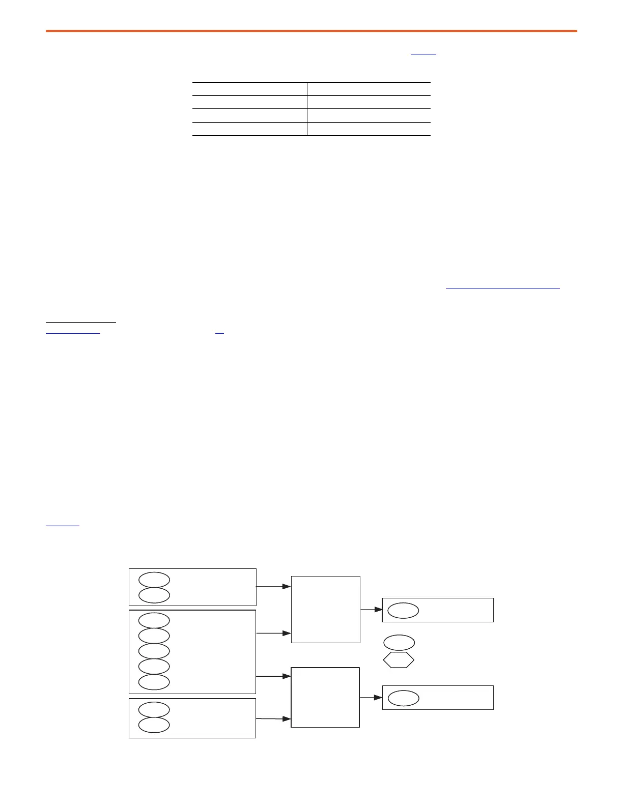
Figure 15
shows how system bandwidth and alternate feedback gain scaler are calculated out of the box and during an autotune bandwidth
calculation.
Figure 15 - System Bandwidth Calculation
Table 1 - Current Regulator Bandwidths
10:445 [VCL CReg BW] 10:425 [PWM Frequency]
375 Hz 4 kHz
250 Hz 2 kHz
125 Hz 1.33 kHz
TorqueLoopBandwidth T
BW
Hz
1
2 DMTC
----------------------------
=
Out-of-box &
[Autotune] =
“BW Calc”
“JMtr BW Calc”
“JTotalBWCalc”
VCL CReg BW
407
Motor Poles
445
Load Ratio
901
Load Coupling
902
907
xxx
1006
System Damping
Alt Encoder EPR
Alt Vel Fb Sel
Encoder EPR
xxx
Pri Vel Fb Sel
1000
Out-of-box &
[Autotune] =
“BW Calc”
“JMtr BW Calc”
“JTotalBWCalc”
906
System BW
1010
Alt Fb GnScale
000
= Read Only
000
= User Entered
Out-of-box &
[Autotune] =
“BW Calc”
“JMtr BW Calc”
“JTotalBWCalc”
VCL CReg BW
407
Motor Poles
445
Load Ratio
901
Load Coupling
902
907
xxx
1006
System Damping
Alt Encoder EPR
Alt Vel Fb Sel
Encoder EPR
xxx
Pri Vel Fb Sel
1000
Out-of-box &
[Autotune] =
“BW Calc”
“JMtr BW Calc”
“JTotalBWCalc”
906
System BW
1010
Alt Fb GnScale
000
= Read Only
000
= User Entered
 Loading...


