82 Rockwell Automation Publication 750-AT006D-EN-P - January 2022
Chapter 6 Active Front End Tuning
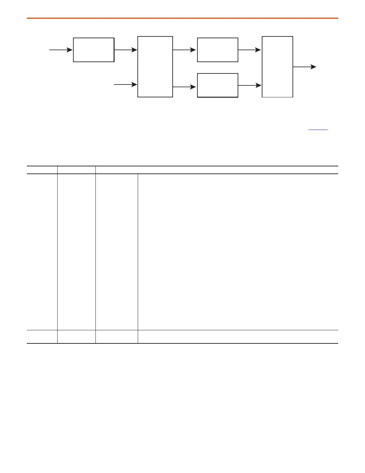
Figure 72 - Simplified AFE Control Block Diagram
Configuration
Depending on the application, the AFE Power converter has several modes of operation for DC bus voltage control, as shown in Table 24.
Select the mode via 13:45 [DC Bus Ref Sel]. In all modes of operation, except for the Active Current Loop, the minimum DC bus commanded
voltage is limited to a value that is calculated based on the auto DC bus reference or the DC bus command voltage is based on the rated
motor voltage. The active current mode is selected by setting 13:40 [Conv Options Config] Bit 2 ActvCurLoop.
Table 24 - DC Bus Reference Selection
Parameter No. Parameter Name Description
13:45 [DC Bus Ref Sel]
DC Bus Reference
Select
Enter a value to select the source for the DC Bus voltage reference.
• 13:45 [DC Bus Ref Sel] = Auto (0) selects an automatically generated reference that is based on the level of
the incoming AC line voltage. This signal comes from 13:46 [Auto DC Bus Ref].
–Default mode
– Recommended for maximum power rating and maximum efficiency.
– The DC bus reference is controlled to ensure the best possible efficient operation of the drive, where the
DC Bus is automatically adjusted to be higher than the peak of the input line voltage by 2%.
– DC bus voltage can fluctuate based on the input line voltages.
• 13:45 [DC Bus Ref Sel] = Manual (1) selects a 'manual' reference in 13:48 [DC BusRef Preset].
– Commanded DC bus reference is limited to a higher value than the Auto DC reference value or to a
maximum value, depending on the frame rating.
• 13:45 [DC Bus Ref Sel] = Droop Ctrl (2) selects a voltage reference generated by Droop Control.
– DC bus voltage is controlled to allow parallel operation of two or more AFE units without them fighting
each other.
– The DC bus command is mainly controlled by the settings of the droop control function and the loading
conditions.
• 13:45 [DC Bus Ref Sel] = VAR Control (3) selects reactive power control.
– DC Bus voltage is controlled based on the reactive power command.
– The DC bus command tends to increase while operating at leading power factor, supplying reactive
power to the grid.
• 13:45 [DC Bus Ref Sel] = DBC Control (4) selects Dynamic Bus Control.
– The DC bus is programmed based on the load cycle to optimize the utilization of the DC capacitance in
servo applications where the system is subjected to high impact loads for short periods of time.
• Active Current Loop
– DC Bus voltage regulator is disabled. Consequently, the DC bus voltage is not controlled.
– In these applications, the DC bus is controlled by external means and the power converter behaves
mainly as a current source.
– This mode is enabled by checking 13:40 [Conv Options Cfg] Bit 2 ActvCurLoop
13:40 [Conv Options Cfg]
Converter Options
Configuration
Bit 2 ActvCurLoop configures the line-side converter to function in Active Current mode.
DC Bus Voltage
Regulator
q-axis Current
Component
Regulator
d-axis Current
Component
Regulator
LCL
Steady-state
Compensaon
kVAR Reference
dq/abc
and
Modulator
 Loading...


