90 Rockwell Automation Publication 750-AT006D-EN-P - January 2022
Chapter 6 Active Front End Tuning
Phase Locked Loop
Phase Locked Loop (PLL) is a control algorithm that is responsible for estimating the grid angle and frequency. Because the AFE operation
and the performance relies heavily on performance of the PLL, it essential that users understand the basic principles of PLL and how to tune
it and adjust its parameters if needed. Typically, for most of the applications, the default parameters will not need to be changed because
these settings can provide the best performance in a typical facility. However, in special circumstances, these parameters can be adjusted
or fine tuned to achieve optimum performance. Unlike the zero-crossing technique that relies on detecting the zero crossing of the input
line voltages, the PLL continuously monitors the input line voltages to provide instantaneous values of the grid angle and frequency. This
enhances the transient response of the AFE converter with respect to line voltages disturbances or variations on the grid.
The PLL relies on measuring the input line voltages of the grid. In many applications, the input line voltages are not perfectly balanced; the
line voltages are balanced when they are equal in magnitude and the phase angle between them is 120°. This can significantly affect the
accuracy of the PLL. A simple way to alleviate this problem is to detune the controller gains in the PLL. Detuning can help reject the second-
order harmonic component that is caused by the unbalance in line voltages of the grid. Detuning can degrade the transient performance of
the PLL, which can affect the AFE converter operation under grid frequency variations/oscillations. The PLL algorithm that is used in the
PowerFlex 755T AFE converter can provide perfect rejection for the unbalance in the grid line voltages while maintaining a B
W
of 100 Hz
(628 rad/sec).
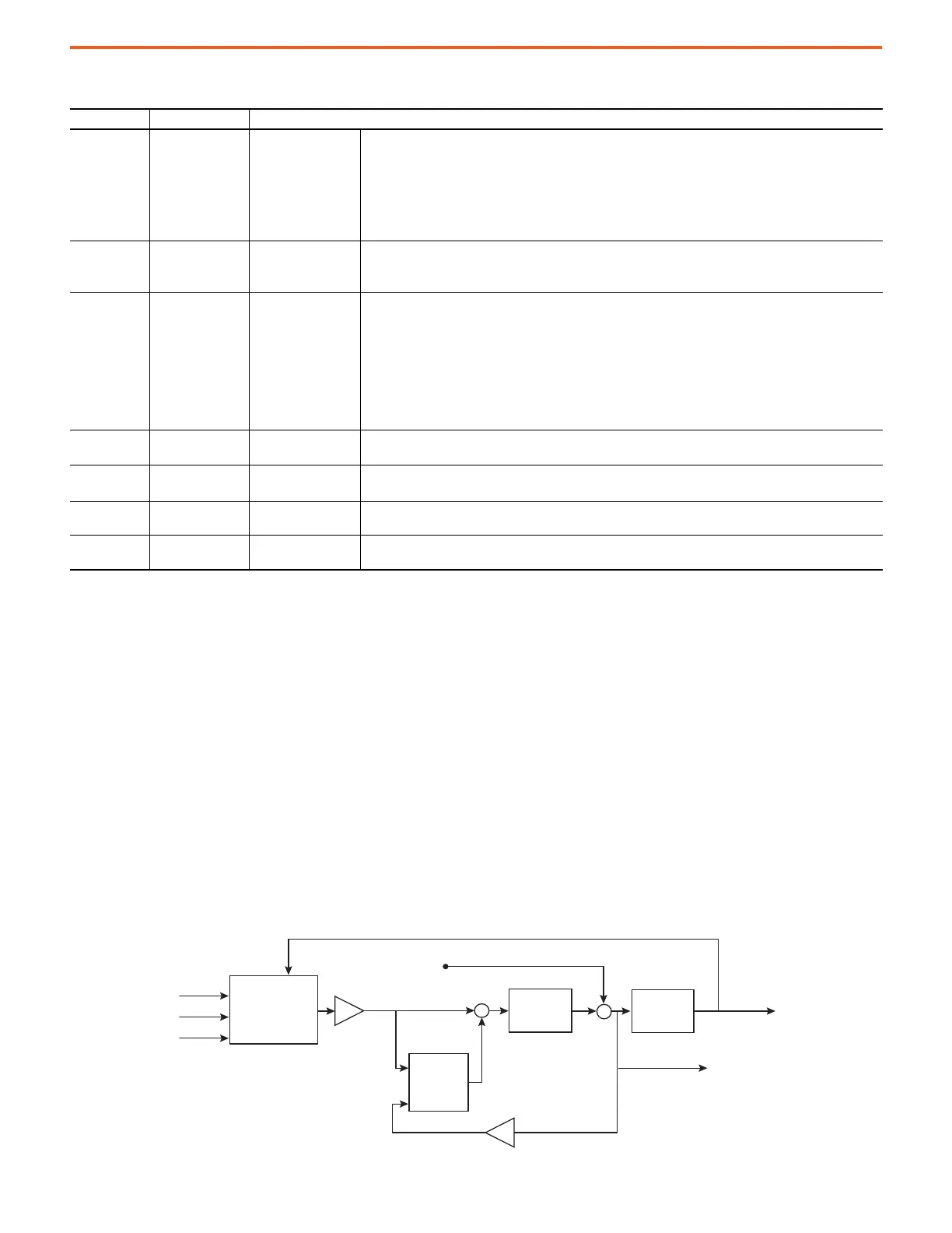
Figure 75 - Function Block Diagram of the PLL with Adaptive Tracking Filter
Table 32 - Parameter Settings for Resonance Mitigation
Parameter No. Parameter Name Description
13:45 [DC Bus Ref Sel]
Feed Forward Voltage
LPF Time Constant
Enter a value to select the source for the DC Bus Voltage reference. Parameter values are as follows.
• Auto (0) – selects an automatically generated reference that is based on the level of the incoming AC line
voltage. This signal comes from 13:46 [Auto DC Bus Ref].
• Manual (1) – selects a manual reference in 13:48 [DC BusRef Preset].
• Droop Ctrl (2) – selects a voltage reference generated by Droop Control
• VAR Control (3) – selects reactive power control
• DBC Control (4) - selects Dynamic Bus Control
13:46 [Auto DC Bus Ref]
Automatically
Optimized DC Bus
Reference
Displays the value of the automatically optimized DC bus reference.
• The DC bus regulator consumes this value when 13:45 [DC Bus Ref Sel] is set to Auto (0).
• The value is based on the level of the incoming AC line voltage. As AC line voltage rises, it also rises.
13:48 [DC BusRef Preset]
DC Bus Reference
Preset
Enter a value to set the constant Preset DC Bus Voltage reference.
• The DC bus regulator consumes this value when 13:45 [DC Bus Ref Sel] is set to Manual (1).
• The maximum value of this parameter is determined by the voltage rating of the converter and the setting
of 0:33 [VoltageClass Cfg]. Parameter values are as follows.
• Converter Rating 0:33 [VoltageClass Cfg] Maximum
– 400/480V Low Voltage (0) 650V DC
– 400/480V High Voltage (1) 712V DC
– 600/690V Low Voltage (0) 975V DC
– 600/690V High Voltage (1) 1024V DC
13:55 [Volt Reg BW]
Voltage Regulator
Bandwidth
Enter a value to set bandwidth of the DC Bus Voltage Regulator.
• This value is used to calculate the calculated proportional and integral gains of the regulator.
13:75 [Cur Reg BW]
Current Regulator
Bandwidth
Enter a value to set bandwidth of the current regulator.
• This value is used to calculate the calculated proportional and integral gains of the regulator.
13:81 [Actv Damping Gn] Active Damping Gain
Enter the value for the proportional gain in the algorithm for active damping of resonant frequencies in the
LCL filters.
13:360 [FFVltgLPFTime]
Feed Forward Voltage
LPF Time Constant
Enter the time constant for the low pass filter used to filter the feed forward voltage components.
+
+
+
-
-1
Zo
Z
e
Output
Frequency
Z
Output
Angle
G'
PI
Regulator
Integrator
ATF
u
V
d
V
ab
V
bc
V
ca
abc/dq
transformaon
2
 Loading...


